DEALER SERVICE The information in this section is written for dealer service personnel. The repair described here requires special skills and tools. If your shop is not properly equipped or your mechanics are not properly trained in this type of repair, you may be time and money ahead to replace complete assemblies.
2. Remove sheave (3) and spacer (4). NOTE: A wheel puller may be needed if sheave can not be removed by hand. Retain key (11). 3. Slide shaft assembly (12), lower bearing (5), and long spacer (10) out the bottom of spindle housing (8). 4. Remove upper bearing (5) and spacer (4) from top of spindle housing.
Before working underneath, read manual instructions, securely block up, and check stability. Secure blocking prevents equipment from dropping due to hydraulic leak down, hydraulic system failure, or mechanical component failure.
5. Inspect parts and replace as needed.
Keep all persons away from operator control area while performing adjustments, service, or maintenance.
Always wear relatively tight and belted clothing to avoid entanglement in moving parts. Wear sturdy, rough-soled work shoes and protective equipment for eyes, hair, hands, hearing, and head; and respirator or filter mask where appropriate.
BLADE SPINDLE REPAIR Spindle repair requires special skills and tools. If your shop is not properly equipped or your mechanics are not trained in this type of repair, you may be time and money ahead to use a new spindle assembly. For reference, the grease fitting is in the top of the spindle shaft. Permatex® 3D Aviation Form-A-Gasket or equivalent is recommended as a sealant.
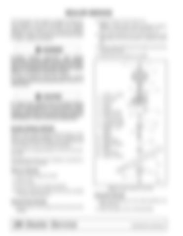
1. 2. 3. 4. 5. 6. 7. 8. 9. 10. 11. 12. 13. 14. 15.
3/8 NF x 1 HHCS Cup washer Sheave Spacer Spindle bearing 3/8 NC Lock nut 1/4 Grease fitting
Spindle housing 3/8 NC x 1-1/2 HHCS
Spacer Square key Shaft assembly Blade Cup washer 5/8 NF x 2 HHCS
Remove Spindle 1. Remove belt shields from deck. 2. Remove belt. 3. Remove blade from spindle assembly. 4. Remove nuts (6) and bolts (9) that secure spindle to mower. (See Figure 8.)
Disassemble Spindle 1. Remove bolt (1) and washer (2) from the top of the spindle.
24 Dealer Service
Figure 8. Blade Spindle Assembly
Assemble Spindle 1. Slide lower bearing (5) over shaft assembly (12) with seal down. 2. Slide long spacer (10) on shaft assembly.
5WPMAN0765 (9/30/2009)


