2 minute read
Hydraulic Latch Release Installation cont.


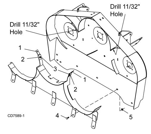
Mulch Kit Installation
NOTE: Do not tighten hardware until mulch kit is completely installed.
1. Raise deck and lock into transport position.
NOTE: Make sure deck is stable before proceeding.
2. Remove chain shielding if installed. Chain shielding is not required when using mulch kit.
3. Attach mulch kit frame to bottom of deck using carriage bolts (4) and flange lock nuts (5). Make sure head of carriage bolts are on the underside of the deck.
NOTE: Rotate blades and check for interference with mulch kit frame. Failure to do so could result damage or possible injury once mower is operated. Adjust frame as necessary.
4. Attach the two support brackets (1) to the mulch kit frame using carriage bolts (2) and flange lock nuts (3). Make sure head of carriage bolt are on the blade side of the frame.
5. Using the support brackets as a template mark and drill two 11/32” holes into the deck baffles.
Figure 20 . Hydraulic Latch Release Installation
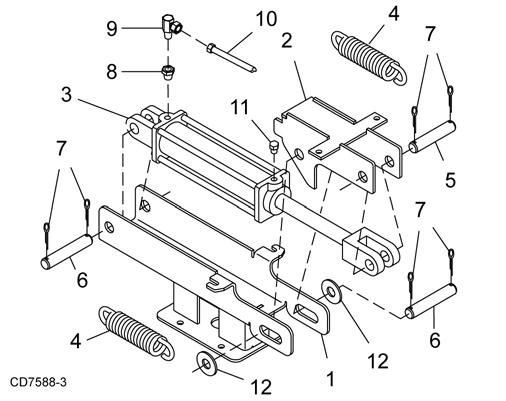
2. Remove plugs from front and rear ports on cylinder and extend cylinder rod.
3. Install vent plug (11) in port near rod end.
4. Place release slide (2) over clevis on rod end of cylinder (3) and secure using pin (5) and two cotter pins (7).
5. Attach base end of cylinder to release base (1) using pin (6) and cotter pins (7).
6. Extend cylinder and align release slide (2) with release base (1). Insert pin (6), two washers (13) and secure using two flat washers (12) cotter pins (7) on the out side.
7. Attach springs (4) between base (1) and slide (2).
8. Install bushing (8) and elbow (9) into port at base of cylinder.Remove the four bolts and washers from the top of gearbox shield.
9. Place latch assembly over gearbox shield, align holes and secure using the hardware previously removed.
10. Remove latch rope from between front latch and tractor.
11. Attach hydraulic hose (10) to elbow (9). Attach male quick coupler to opposite end of hose. NOTE: quick coupler is not included in this kit.
6. Secure support brackets to baffles using carriage bolts (2) and flange lock nuts (3). Make sure head of carriage bolts are on the blade side of the frame.
7. Tighten all hardware.
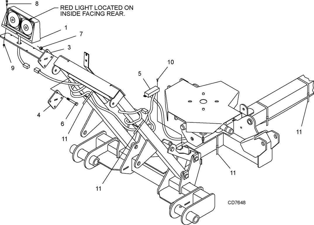
Light Kit Installation
1. Install wire harness (5) to bracket on trailer frame using #10 x 1/2” tapping screws (10).
2. Route wires as shown. Be sure wire labeled “left” is routed to the left side of the unit. Wrap excess wire around center deck frame tubes as shown.
3. Clamp light brackets (3) to center deck frame tubes using mounting blanks (4), 3/8” x 3-1/2” cap screws (6) and 3/8” flange lock nuts (7).
4. Secure left and right lamp (1 and 2) to brackets using 1/4” x 1” cap screws (8) and 1/4” lock nuts (9).
5. Connect lights to wiring harness.
6. Pull any slack out of main wire and install cable ties (11) to trailer as shown.
7. Extra slack in the light wires should be located near the wiring harness. Make sure wires cannot become entangled in the driveline or hydraulic cylinder. Secure wires to frame tubes above cylinder and lock with cable ties (11) as shown.
1.Light, 4 Pin Right
2.Light, 4 Pin Left
3.Light Bracket
4.Mounting Blank
5.Wire Harness
6.3/8” x 3-1/2” Hex Head Cap Screw
7.3/8” Flange Lock Nut
8.1/4” x 1” Hex Head Cap Screw
9.1/4” Lock Nut
10.#10 x 1/2” Tapping Screw
11.Cable Tie