10 minute read
DEALER SERVICE


The information in this section is written for dealer service personnel. The repair described here requires special skills and tools. If your shop is not properly equipped or your mechanics are not properly trained in this type of repair, you may be time and money ahead to replace complete assemblies.
Before working underneath, read manual instructions, securely block up, and check stability. Secure blocking prevents equipment from dropping due to hydraulic leak down, hydraulic system failure, or mechanical component failure.
Keep all persons away from operator control area while performing adjustments, service, or maintenance.
2. Remove sheave (3) and spacer (4). NOTE: A wheel puller may be needed if sheave can not be removed by hand. Retain key (11).
3. Slide shaft assembly (12), lower bearing (5), and long spacer (10) out the bottom of spindle housing (8).
4. Remove upper bearing (5) and spacer (4) from top of spindle housing.
5. Inspect parts and replace as needed.
1. 3/8 NF x 1 HHCS
2. Cup washer
Always wear relatively tight and belted clothing to avoid entanglement in moving parts. Wear sturdy, rough-soled work shoes and protective equipment for eyes, hair, hands, hearing, and head; and respirator or filter mask where appropriate.
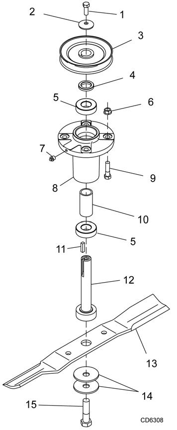
Blade Spindle Repair
Spindle repair requires special skills and tools. If your shop is not properly equipped or your mechanics are not trained in this type of repair, you may be time and money ahead to use a new spindle assembly. For reference, the grease fitting is in the top of the spindle shaft.
Permatex® 3D Aviation Form-A-Gasket or equivalent is recommended as a sealant.
Remove Spindle
1. Remove belt shields from deck.
2. Remove belt.
3. Remove blade from spindle assembly.
4. Remove nuts (6) and bolts (9) that secure spindle to mower. (See Figure 8.)
Disassemble Spindle
1. Remove bolt (1) and washer (2) from the top of the spindle.
3. Sheave
4. Spacer
5. Spindle bearing
6. 3/8 NC Lock nut
7. 1/4 Grease fitting
8.Spindle housing
9. 3/8 NC x 1-1/2 HHCS
10.Spacer
11.Square key
12.Shaft assembly
13.Blade
14.Cup washer
15. 5/8 NF x 2 HHCS
Assemble Spindle
1. Slide lower bearing (5) over shaft assembly (12) with seal down.
2. Slide long spacer (10) on shaft assembly.
3. Insert shaft assembly with bearing and spacer into spindle housing from the bottom.
4. Install upper bearing (5) over shaft with the seal facing up.
5. Install spacer (4) and sheave (3) over shaft.
6. Align keyways in shaft and sheave and insert key (11).
7. Install washer (2), and bolt (1). Torque bolt to 35 lbs-ft.
8. Rotate sheave and check for free movement.
9. Lubricate spindle.
Gearbox Repair
Read this entire section before starting any repair. Many steps are dependent on each other.
Fill gearbox with SAE 80W or 90W gear lube until it runs out the side level plug.
Repair to this gearbox is limited to replacing bearings, seals, and gaskets. Replacing gears, shafts, and a housing is not cost effective. It is more economical to purchase a complete gearbox if repair to anything other than replacement of bearings, seals or gaskets is required.
Inspect gearbox for leakage and bad bearings.
Leakage is a very serious problem and must be corrected immediately.
Bearing failure is indicated by excessive noise and side to side or end play in gear shafts.
Seal Replacement
Recommended sealant for gearbox repair is Permatex® Aviation 3D Form-A-Gasket or equivalent.
Leakage can occur at the vertical or horizontal gaskets and shaft seals.
Leakage at the horizontal gasket or seal can be repaired without removing the gearbox from the mower.
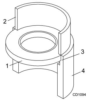
Seal Installation
NOTE: Proper seal installation is important. An improperly installed seal will leak.
1. Clean area in housing where seal outer diameter (OD) seats. Apply a thin coat of Permatex.
2. Inspect area of shaft where seal seats. Remove any burrs or nicks with an emery cloth.
3. Lubricate gear shaft and seal lips.
4. Place seal squarely on housing, spring-loaded lip toward housing. Select a piece of pipe or tubing with an OD that will sit on the outside edge of the seal but will clear the housing. Tubing with an OD that is too small will bow seal cage and ruin seal.
5. Carefully press seal into housing, avoiding distortion to the metal seal cage.
1.Seal
2.Pipe or tube
3.Seal seat
4.Casting
Pipe or tube must press at outer edge of seal.
Incorrect Installation
Installation
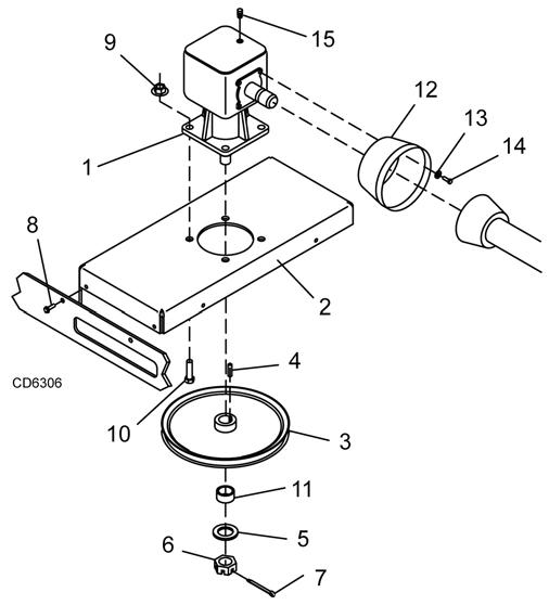
Vertical Shaft Seal Replacement
Refer to Figure 10.
1. Disconnect and remove the driveline from the gearbox.
2. Remove vent plug (15) and siphon gear lube from housing through this opening.
3. Remove gearbox stand from mower deck.
4. Remove gearbox and pulley from stand (2).
5. Remove vertical shaft seal. Replace with new seal (see Seal Replacement, page 25).
Vertical seal should be recessed in housing. Horizontal seal should be pressed flush with outside of housing.
NOTE: Distortion to seal cage or damage to seal lip will cause seal to leak.
6. Fill gearbox with SAE 80W or 90W gear lube until it runs out the level plug.
7. Assemble gearbox and pulley to gearbox stand. Attach gearbox stand to mower deck.
Horizontal Shaft Seal Replacement
1. Disconnect and remove the driveline from the gearbox.
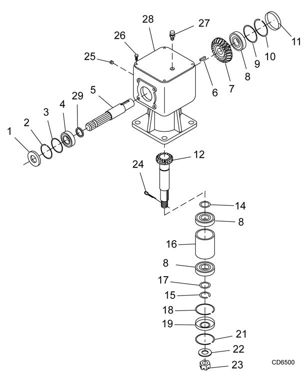
2. Remove vent plug (27), Figure 11, and siphon gear lube from housing through this opening.
3. If the leak occurred at either end of horizontal shaft, remove oil cap (11) and/or oil seal (1). Replace with new one (see Seal Replacement, page 25).
4. Fill gearbox with SAE 80W or 90W gear lube until it runs out the level plug.
Remove Gearbox from Mower
1. Disconnect and remove the rear driveline from the gearbox.
2. Remove vent plug (15), Figure 10, and siphon gear lube from housing through this opening.
3. Remove gearbox stand (2) from mower deck by removing four hex screws (8).
4. Remove four cap screws (14) and washers (13) and remove shield (12) from gearbox.
5. Remove castle nut (6) and hardware from output shaft of gearbox.
6. Remove sheave (3) from gearbox.
7. Remove four bolts (10) that attach gearbox to gearbox stand and remove gearbox.
Disassemble Gearbox
Refer to Figure 11.
1. Remove top cover (28) from housing. Turn gearbox upside down and pour out remaining gear oil from gearbox.
2. Remove oil cap (11) (to be replaced).
3. Remove snap ring (10) and shim (9) from input shaft (5).
4. Support gearbox in hand press and push on input shaft (5) to remove bearing (8).
5. Remove gear (7) from inside housing.
6. Remove oil seal (1) from front of housing (to be replaced).
7. Remove snap ring (2) and shim (3) from front of housing.
8. Remove input bearing (4) by using a punch and hammer from outside of housing.
9. Support housing in vise in a horizontal position.
10. The castle nut (23) and cotter pin (24) are already removed with the drive sheave. Remove the snap ring (18) and seal (19).
11. Remove output shaft (12) and bearings by using a punch and hammer and tap on top to drive down.
12. Inspect gears for broken teeth and wear. Some wear is normal and will show on laded side. Forged gear surfaces are rough when new. Check that wear pattern is smooth.
13. Inspect vertical and horizontal shafts for grooves, nicks, or bumps in the areas where the seals seat. Resurface any damage with emery cloth.
14. Inspect housing and caps for cracks or other damage.
Reassemble Gearbox
NOTE: Repair to this gearbox is limited to replacing bearings, seals, and gaskets. Replacing gears, shafts, and a housing is not cost effective. Purchasing a complete gearbox is more economical.
1. Clean housing, paying special attention to areas where seals will be installed.
2. Wash housing and component thoroughly. Select a clean area for gearbox assembly. Replace all seals and bearings. All parts must be clean and lightly oiled before reassembling.
3. Install shims (14), upper output bearing (8), spacer (16), lower output bearing (8), shims (17), and snap ring (15) on output shaft. Use new shims equal to the thickness of the original shims.
4. Press output shaft assembly into housing from the bottom opening.
5. Install snap ring (18) in bottom of housing.
6. Apply grease to lower seal lips (19), and press seal over output shaft (12), using a round tube of the correct diameter. Be sure not to damage the seal lip. Press in housing so that the seal is recessed.
7. Install snap ring (21) and position it together with seal (19) by pressing it into position. Verify that the snap ring is seated properly.
8. Press bearing (8) into the housing, using a round tube of the correct diameter and a hand press. Secure with shims (9) and snap ring (10).
9. Install key (6) on input shaft (5).
10. Place gear (7) through top of housing and align the two gears so they match.
11. While holding gear (7) in place, slide input shaft (5) through the gear and bearing (8).
12. Slide spacer (29) and bearing (4) over input shaft (5) and press into housing, using a round tube of the correct diameter and a hand press.
13. Slide shim (3) over input shaft and secure with snap ring (2).
14. Check input shaft end float by moving the input shaft by hand. If the end float is more than .012", insert shim (9) between the rear bearing (8) and snap ring (10).
15. Check that gear backlash is between .006" and .016". You should not have to adjust the backlash.
16. Press in input seal (1), using a round tube of the correct diameter. Be careful not to damage the seal lip.
17. Press oil cap (11) on to the rear cover of housing, using a round tube of the correct diameter.
18. Check the gearbox housing for leaks by plugging all holes except one. Apply 4 psi compressed air and immerse the gearbox in water to verify that there are no leaks.
19. Remove the gearbox from water and dry off with compressed air. Add SAE 80W or 90W EP oil until it runs out of the side level hole. Tighten all plugs.
5WPMAN0765 (9/30/2009)
Install Gearbox
NOTE: Gearbox is heavy: do not attempt to move without mechanical assistance.
1. Set gearbox on gearbox stand and fasten with bolts and nuts. Torque bolts to 175 lbs-ft.
2. Attach drive sheave to output shaft. Secure using castle nut and hardware previously removed.
3. Attach gearbox stand to mower using four hex screws.
Install Drive Sheave
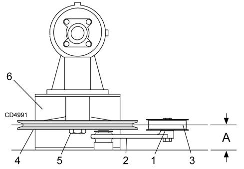
1. When gear stand is installed on mower, dimension A (from the top of the mower deck to the center line of the drive pulley) must be 2-1/16" (±1/32"). This is a critical dimension and must be carefully adjusted for proper belt life. Add or subtract shim washers under idler pulley to align with drive pulley.
2. Tighten gear stand hardware.
3. Fill gearbox half full with SAE 90W gear lube.
4. Check level after waiting five minutes to permit lube to work through bearings. Add lube, if necessary, until gearbox is half full.
5. Replace driveline shield. Attach driveline to gearbox.
1.Shim
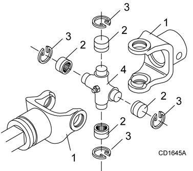
Universal Joint Repair
1. Yoke
2. Cup and bearings
3. Snap ring
4. Journal cross
U-Joint Disassembly
1. Remove external snap rings from yokes in four locations as shown in Figure 14.
2. With snap rings removed, support drive in vise, hold yoke in hand and tap on yoke to drive cup up out of yoke. See Figure 15.
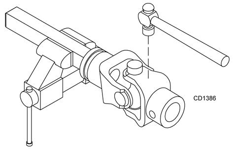
3. Clamp cup in vise as shown in 4. and tap on yoke to completely remove cup from yoke. Repeat Step 2 & Step 3 for opposite cup.
shaft. Be careful not to disturb needle bearings. Insert another bearing cup directly across from first cup and press in as far as possible with hand pressure.
2. Trap cups in vise and apply pressure. Be sure journal cross is started into bearings and continue pressure with vise, squeezing in as far as possible. Tapping the yoke will help.
3. Seat cups by placing a drift or socket (slightly smaller than the cup) on cup and rap with a hammer. See Figure 18. Install snap ring and repeat on opposite cup.
4. Repeat Step 1 & Step 2 to install remaining cups in remaining yoke.
5. Move both yokes in all directions to check for free movement. If movement is restricted, rap on yokes sharply with a hammer to relieve any tension. Repeat until both yokes move in all directions without restriction.
4. Place universal cross in vise as shown in Figure 17 and tap on yoke to remove cup. Repeat Step 3 for final removal. Drive remaining cup out with a drift and hammer.
U-Joint Assembly
1. Place seals securely on bearing cups. Insert cup into yoke from outside and press in with hand pressure as far as possible. Insert journal cross into bearing cup with grease fitting away from
Assembly Instructions
DEAL ER SET-UP INSTRUCTIONS
The mower is shipped mostly assembled but requires dealer set-up. The dealer should deliver the mower to the owner completely assembled, lubricated, and adjusted for normal conditions.
Recommended torque values for hardware are located on page52.
Complete check lists on page33 when assembly is complete.
Keep hands and body away from pressurized lines. Use paper or cardboard, not hands or other body parts to check for leaks. Wear safety goggles. Hydraulic fluid under pressure can easily penetrate skin and will cause serious injury or death.
Make sure that all operating and service personnel know that if hydraulic fluid penetrates skin, it must be surgically removed as soon as possible by a doctor familiar with this form of injury or gangrene, serious injury, or death will result. CONTACT A PHYSICIAN IMMEDIATELY IF FLUID ENTERS SKIN OR EYES. DO NOT DELAY.
Make sure spring-activated locking pin or collar slides freely and is seated firmly in tractor PTO spline groove.
Attach Hydraulic Hoses
Air in hydraulic systems can cause erratic operation and allows loads or equipment components to drop unexpectedly. When connecting equipment or hoses or performing any hydraulic maintenance, purge any air in hydraulic system by operating all hydraulic functions several times. Do this before putting into service or allowing anyone to approach the equipment.
Attach the mower hydraulic hose to the tractor port. Hydraulic quick coupler is not supplied.
NOTE: The mower hydraulic system should have been filled at the factory. Always assume it is empty. Fully purge air and fill the hydraulic system by raising and lowering wings several times while hooked to a tractor hydraulic supply. Keep all personnel away while raising and lowering.
Optional Equipment
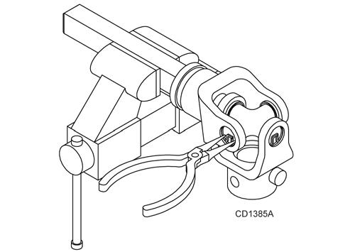
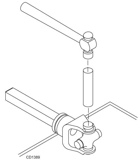
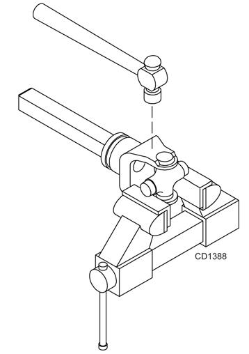
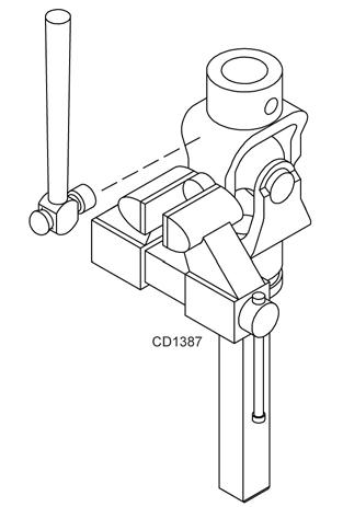
Hydraulic Latch Release Installation
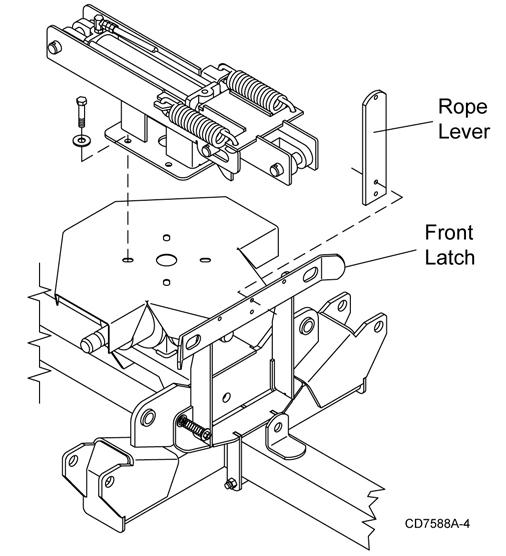
1. Remove rope lever from the top of front latch.
Always wear relatively tight and belted clothing to avoid getting caught in moving parts. Wear sturdy, rough-soled work shoes and protective equipment for eyes, hair, hands, hearing, and head; and respirator or filter mask where appropriate.
Remove Shipping Straps
1. Remove CV drive from rear wing frame.
2. Attach drive to splitter gearbox. Position CV joint towards the tractor. See page36 for orientation.
3. Remove shipping straps from front and rear of right and left wing decks.
4. Remove parking jack from storage position on left wing.
5. Attach parking jack to trailer tongue frame.
6. Remove wood block from hitch.