12 minute read
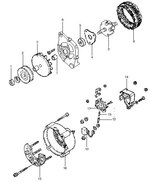
Carburetor,Gasoline

Cylinder Block Plug Installation Installation Procedure Tools Required • J 41712 Oil Pressure Switch Socket C AU TIO N!
Caution:Wear safety glasses in order to avoid eye damage.
1. Install a new oil filter bypass valve. a.Install the oil filter bypass valve into the oil gallery bore until slightly below flush with the surface of the engine block. b.Using a pointed punch, stake the engine block area around the oil filter bypass valve. Stake in 3 locations 120 degrees apart. 2. Apply sealant MCF P/N 2I4256 GMP/N 12346004 or equivalent to the outside diameter of the new front engine oil gallery plugs. 3. Install the new front engine block oil gallery plugs.
A properly installed front engine oil gallery plug must be installed slightly below flush with the front face of the engine block.
4. Install the spring type S pin (crankshaft rear oil seal housing locator) (if required).
-79-
5. Apply sealant MCF P/N 2I4256/GMP/N 12346004 or equivalent to the outside diameter of the new expansion cup plug (balance rear bearing hole). 6. Install the new expansion cup plug (balance shaft rear bearing hole).
7. Apply sealant MCF P/N 2I4256/GMP/N 12346004 or equivalent to the outside diameter of the new expansion cup plug (camshaft rear bearing hole). 8. Install the new expansion cup plug (camshaft rear bearing hole). Tightening torque Left for left and right 2.08 Kgf•m (15 lbf•ft) [20 N•m] rear oil gallery plug Right 3.05 Kgf•m (22 lbf•ft) [30 N•m]
9. Apply sealant MCF P/N 2I4256 GMP/N 12346004 or equivalent to the threads of the engine block right rear oil gallery plug, the engine block left rear oil gallery plug, and the engine block left side oil gallery plug. 10.Install the engine block right rear oil gallery plug, the engine block left rear oil gallery plug, and the engine block left side oil gallery plug.
Tighten the engine block left side oil gallery plug
and the engine block right rear oil gallery plug 11.Install the dowel straight pins (transmission locator) (if required).
NO TE
-80-
12.Install the left side dowel pins (cylinder head locator) (if required). 14.Apply sealant MCF P/N 2I4256/GMP/N 12346004 or equivalent to the threads of the engine block coolant drain hole plug. 15.Install the engne block coolant drain hole plug.
Tightening torque engine block 2.08 Kgf•m (15 lbf•ft) [20 N•m] coolant drain hole plug
13.Install the right side dowel pins (cylinder head locator) (if required).
-81-
16.Apply sealant MCF P/N 2I4256/GMP/N 12346004 or equivalent to the threads of the engine oil pressure sensor fitting.
Important: Do not loosen the engine oil pressure fitting after the initial torque has been obtained. 17.Install the engine oil pressure sensor fitting.
Important: Do not rotate the engine oil pressure fitting clockwise more than 359 degrees after the initial torque has been obtained. 18.Rotate the engine oil pressure sensor fitting clockwise to the proper position 19.Apply sealant MCF P/N 2I4256/GMP/N 12346004 or equivalent to the threads of the engine oil pressure gauge sensor. 20.Install the engine oil pressure gauge sensor using the J 41712. 21.Apply sealant MCF P/N 2I4256/GMP/N 12346004 or equivalent to the threads of the knock sensor.
NO TE 22.Install the knock sensor. NO TETightening torque for engine oil 1.52 Kgf•m (11 lbf•ft) [15 N•m] pressure sensor fitting Tightening torque for engine oil 3.05 Kgf•m (22 lb•ft) [30 N•m] pressure gauge sensor Tightening torque 2.08 Kgf•m (15 lbf•ft) [20 N•m] for knock sensor
-82-
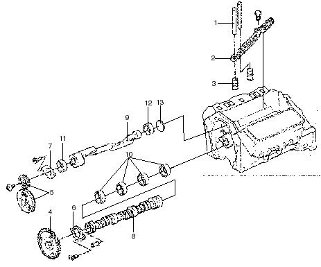
Piston and Connecting Rod
Removal and Installation
5
6
4 8 9
T=4.3-6.0 kgf-m (31.1-43.4 lbf-ft) [42-59 N•m]
7
Removal steps
1.Nut 2.Rod Cap 3.Bearing 4.Bearing 5.Piston and Connecting Rod Assy 6.Pin 7.Rod - Connecting 8.Piston 9.Ring Kit 3 2 1
-83-
Piston,Connecting Rod,and Bearing Removal
Tools Required
• MCF-1064 (J 5239) Guide Set 1. Remove the ring ridge. a.Turn the crankshaft until the piston is at the bottom of the stroke. b.Place a cloth on top of the piston. c.Use a ridge reamer to remove cylinder ring ridge. d.Turn the crankshaft so the piston is at the top of the stroke. e.Remove the cloth. f.Remove the cutting debris. 2. Remove the connecting rod nuts. 3. Remove the connecting rod cap.
Important: Place matchmarks or numbers on the connecting rods and the connecting rod caps. Assemble the connecting rod caps to the matching connecting rods.
4. Remove the connecting rod bearings. • Keep the bearings with the original connecting rod and connecting rod cap. • Wipe the oil from the bearings. • Wipe the oil from the crankpins. 5. Use the MCF-1064 (J 5239) to remove the connecting rod and the piston out of the top of the engine block.
MCF-1064 (J 5239)
NO TE
-84-
Piston and Connecting Rod Disassembly Tools Required • MCF-1083 (J 24086-C) Piston Pin Removal Set NO TE Important: Mark the piston for installation to the proper cylinder.
1. Remove the piston rings from the pistons. 2. Remove the pin from the piston.
Piston and Connecting Rod Clean and Inspect
1. Clean the connecting rod in cleaning solvent. 2. Dry the connecting rod with compressed air. 3. Clean the varnish from the piston skirts and the pins with the cleaning solvent. 4. Clean the piston ring grooves with a groove cleaner. 5. Do not use a wire brush to clean any part of the piston. 6. Clean the piston oil ring holes and the slots. 7. Inspect the connecting rod for twisting, nicks, and cracks.Replace any damaged connecting rods. 8. Inspect the pistons for the following conditions. • Cracked ring lands, skirts, or pin-bosses. • Nicks or burrs in the grooves that may cause binding.
MCF-1083 (J 24086-C)
-85-
Piston Selection
1. Measure the piston-to-cylinder bore clearance to determine the suitability of a used piston. 2. Measure the piston-to-cylinder bore clearance as follows. a.Use a boring gauge to measure the cylinder bore diameter at a point of 66 mm (2.5in.) from the top of the cylinder bore. b.Use a micrometer or caliper to measure the piston 11.5 mm (0.45 in.) from the bottom of the skirt at right angles to the piston pin. c.Subtract the piston diameter from the cylinder bore diameter to indicate piston-to-bore clearance. d.Compare the measurements to specifications. e.Mark the piston for installation to the proper cylinder. f.A used piston may be installed, if clearances are within specifications.
Piston,Connecting Rod and Bearing Installation
Tools Required
• MCF-1064 (J 5239) Guide Set • MCF-1068 (J 8037) Piston Ring Compressor • MCF-1074 (J 36660) Torque Angle Meter 1. Coat the following components with clean engine oil: • The piston • The piston rings • The cylinder bore • The bearing surfaces 2. Install the piston with the stamped arrow facing forward. 3. Install the piston assembly into its matched bore.
When assembled, the flanges on the connecting rod and cap should face the front in the left bank and the rear in the right bank.
-86-
4. Use the MCF-1068 (J 8037) and the MCF-1064 (J 5239) to lightly tap the top of the piston with a wooden hammer handle. a.Hold the MCF-1068 (J 8037) firmly against the engine block until all of the piston rings enter the cylinder bore.
MCF-1068 (J 8037)
b.Use the MCF-1064 (J 5239) to guide the connecting rod onto the crankshaft journal. 5. Remove the MCF-1064 (J 5239).
MCF-1064 (J 5239)
6. Install the connecting rod cap and nuts.
Tightening torque 1st pass for rod cap nuts 2.77 Kgf•m (20 lbf•ft) [27 N•m] • On the final pass, use the MCF-1074 (J 36660) to tighten the nuts an additional 70degrees. 7. When all of the connecting rod bearings are installed, tap each connecting rod assembly lightly parallel to the crankpin to make sure they have clearance.

-87-
8. Use a feeler gauge or a dial indicator to measure the side clearance between the connecting rod caps.The rod side clearance should be 0.160.43mm (0.006-0.017 in.).
Piston and Connecting Rod Assembly
Important: After the MCF-1083 (J 24086-C) installer hub bottoms on the support assembly, do not exceed 35,000 kPa (5000 psi) or the tool may be damaged. Important: When assembling the piston and connecting rod, the mark on the top of the piston must point to the front of the engine block.The flange on the connecting rod must face the front of the piston on the left hand assembly and face the rear of the piston on the right hand assembly. 1. Install the piston pin and connecting rod assembly. a.Lubricate the piston holes in both the piston and the connecting rod assembly. b.Press the piston pin into the piston and connecting rod assembly using the MCF-1083 (J 24086-C). c.Inspect the piston on the piston pin for freedom of movement.
NO TE NO TE
MCF-1083 (J 24086-C)
2. Install the piston rings onto the piston.The marked side of the piston rings must face the top of the piston. 3. Use the following procedure to locate the piston ring gaps. a.Install the oil ring spacer in the groove. b.Hold the spacer ends together and properly locate the gap to install the lower oil ring rail. c.Properly locate the gap and install the upper oil ring rail. d.Flex the oil ring assembly to make sure the rings are free. e.Install the lower compression ring. f.Install the upper compression ring. 4. Install the compression piston rings with the ring gaps 120 degrees apart.Stagger the end gaps on the oil control rings.
-88-
Carburetor,Gasoline
Removal and Installation
1 2
1.Carburetor 2.Fuel Inlet 3.Intake Air Connector 4.Accelerator Cable 5.Carburetor Connector 6.Gasket 7.Adapter 8.Gasket 3
4
T=2.8 kgf•m (20 lb•ft) [28 N•m]
6 5
T=2.5 kgf•m (18 lb•ft) [25 N•m]
7
8
-89-
Removal Procedure
1. Remove Intake Air Connector 2. Disconnect Accelerator Cable from Carburetor 3. Disconnect Carburetor Connector
Hint:Before disconnecting the emission control hoses, use tag to identify how they should be reconnected.
4. Disconnect the Following Hoses: • Fuel inlet hose • Emmision control hoses • Vacuum Laines 5. Remove the four carburetor mounting nuts. 6. Lift out the carburetor. 7. Cover the inlet hole of the intake manifold with a cloth.
-90-
Carburetor Assembly(Upper)
Removal and Installation
Disassembly steps
1.Stud bolt 2.Nipple union 3.Pivot bolt 4.Acceleration pump arm 5.FICB link 6.Air Horn 7.Wire clamp 8.Pivot pin 9.Wire 10.Float 11.Plunger 12.Spring 13.Needle valve 14.Acceleration pump plunger 15.Plunger boot 16.Air horn gasket 17.Needle valve seat 18.Gasket 19.Screw 20.Retainer 21.Power piston 22.Spring 23.Primary upper slow jet 24.Screw 25.Coil housing 26.Gasket 27.Screw 28.Cover 29.Spring 30.E-ring 31.Stopper 32.Spring 33.Collar 34.Diaphragm 35.Solenoid Valve 36.Gasket 37.Screw 38.Choke lever 39.Screw 40.Thermostat housing

-91-
Carburetor Assembly(Lower)
Removal and Installation
Disassembly steps
1.Discharge weight 2.Spring 3.Check ball 4.Plunger spring 5.Retainer 6.Check ball 7.Primary slow jet 8.Plug 9.Spring 10.Ball 11.Plug 12.Ball 13.Power valve 14.Passage plugs 15.Gaskets 16.Primary main jet 17.Gasket 18.Passage ring 19.Screw 20.Primary small venturi 21.Gasket 22.Snap ring 23.Screw 24.Fast idle cam breaker (FICB) 25.Fast idle cam 26.Passage screw 27.Bolt 28.Carburetor Body 29.Carburetor flange 30.Insulator

-92-
Carburetor Disassembly
Hint: The following instructions are organized to allow work on only one component group at a time.This will help avoid confusion between similar looking parts from different subassemblies that are on the workbench at the same time.
1. To facilitate reassembly, arrange parts in order. 2. Be careful not to mix up or lose balls, clips or springs. 3. Use SST carburetor driver set.
Air Horn Disassembly
1. Remove Carburetor Stud Bolt and Nipple Union
2. Remove Acceleration Pump Arm a.Remove the snap ring from the pump connecting link. b.Remove the pivot bolt. c.Disconnect the pump arm from the pump plunger. d.Disconnect the pump connecting link from the throttle lever and remove the pump arm and pump connecting link. 3. Disconnect Fast Idle Cam Breaker (FICB) Link
4. Remove Air Horn Assembly a.Remove the seven screws and following parts: •Number plate (1) •Wire clamps (2) •Switch harness clamp (3) •Coil housing and solenoid valve harness clamp (4) b.Lift off the air horn assembly together with the air horn gasket.
5. Remove Float and Needle Valve
Remove the float pivot pin, float and needle valve subassembly
-93-
6. Remove Acceleration Pump Plunger a.Remove the pump plunger and boot. b.Remove air horn gasket.
7. Remove Needle Valve Seat a.Remove the needle valve seat and gasket.
8. Remove Power Piston a.Remove the screw, retainer, power piston and spring. 9. Remove Primary Upper Slow Jet
10.Disconnect Wires from Carburetor Connector a.Pry up the locking lugs with a screwdriver and pull out the terminal. 11.Remove Coil Housing a.Remove the three screws, retainer, coil housing and gasket.
12.Remove Choke Breaker (CB) a.Remove the three screws, cover and spring.
-94-
b.Remove the E-ring, stopper, spring collar and diaphragm 15.Remove Fast Idle Cam Breaker (FICB)Link a.Remove the screw and FICB link.
13.Remove Fuel Cut Solenoid Valve a.Remove the solenoid valve and gasket.
14.Remove Thermostat Housing a.Remove the screw and choke lever.
b.Remove the two screws and thermostat housing.
Carburetor Body Disassembly
1. Remove Check Balls for Acceleration Pump a.Remove the pump discharge weight, spring and large ball. b.Remove the plunger spring.
c.Using tweezers, remove the ball retainer. d.Remove the small ball.
-95-
2. Remove Slow Jets a.Remove the primary slow jet. b.Remove the primary main jets and gaskets.
3. Remove Check Balls for Auxiliary Acceleration
Pump (AAP) a.Remove the plug, spring and ball (a). b.Remove the plug and ball (b).
4.Remove Power Valve 6. Remove Small Venturies a.Remove the passage ring.
b.Remove the two screws, primary small venturi and gasket.
5. Remove Primary Main Jets a.Remove the two passage plugs and gaskets. 7. Remove Fast Idle Cam Breaker (FICB) a.Remove the snap ring. b.Remove the two screws. c.Disconnect the link, and remove the FICB
-96-
8. Remove Fast Idle Cam
9. Separate Carburetor Body and Flange a.Remove the passage screw and spring washer.
General Cleaning Procedure
1. Clean Disassembled Parts Before Inspection a.With a soft brush, wash and clean the cast parts in carburetor cleaner. b.Clean the carbon around the throttle valve. c.Thoroughly wash the other parts in carburetor cleaner. d.Blow all dirt and other foreign material from the jets, fuel passages and restrictions in the body.
b.Remove the two bolts. c.Separate the body and flange. d.Remove the insulator.
Carburetor Inspection
1. Inspect Float and Needle Valve a.Inspect the pivot pin (1) for scratches and excessive wear. b.Inspect the float (2) for broken lips and wear in the pivot pin holes. c.Inspect the spring (3) for breaks and deformation. d.Inspect the needle valve (4) and plunger (5) for wear or damage. e.Inspect the strainer (6) for rust and breaks.
-97-
2. Inspect Power Piston a.Check that the power piston moves smoothly. 5. Inspect Choke Heater (Coil Housing) a.Using an ohmmeter, measure the resistance between the terminals. Resistance (Cold): 17.3 - 18.7 at 20°C (68°F) If a problem is found, replace the choke heater.
3. Inspect Power Valve a.Check for faulty opening and closing action.
4. Inspect Fuel Cut Solenoid Valve a.Connect the connector terminals to the battery terminals. b.You should feel a “click”from the solenoid valve when the battery power is connected and disconnected.If the solenoid valve is not operating properly, replace it.
Carburetor Assembly
Hint:Use new gaskets and O-rings throughout.
1. Assemble Carburetor Body and Flange a.Assemble the flange and body together with a new insulator. b.Install the two bolts.
c.Install the passage screw together with the spring washer.
-98-