23 minute read
Fuel System - LP

Starter Motor
Removal and Installation
Advertisement
6
4 5

3
2
1
Removal Steps
1.Bolt 2.Spring Washer 3.Starter Motor 4.Cord 5.Starter Harness 6.Starter Relay
-126-
Starter Motor Testing
Electrically the motor consists of the brush assembly and the armature.The solenoid contains pull-in and hold-in windings, and the motor external wiring is the same as field-coil motors.No periodic maintenance or lubrication is required.
In the basic circuit, the solenoid windings are energized when the switch is closed.The resulting plunger and shift lever movement causes the pinion to engage the engine flywheel ring gear and the solenoid main contacts to close, and cranking takes place. When the engine starts, pinion overrun protects the armature from excessive speed until the switch is opened, at which time the return spring causes the pinion to disengage.To prevent excessive overrun, the switch should be opened immediately when the engine starts.
Troubleshooting
Cranking Circuit
Before removing any unit in a cranking circuit for repair, the following checks should be made.
Battery: Ensure that the battery is fully charged, and that it passes the load test.The starting motor cannot operate properly if the battery is discharged or defective. Wiring: Inspect the wiring for damage.Inspect all connections to the cranking motor, solenoid, ignition switch or any other control switch, and battery, including all ground connections.To eliminate any excessive resistance, disconnect and wire brush all wiring connectors in the cranking circuit.This will ensure optimum performance from the wiring.Cables, when properly attached at the battery side terminals, are sealed and normally required no periodic maintenance attention.
Switches: Inspect all switches to determine their condition.With switches closed, use a voltmeter to check the circuit for continuity.Replace defective switches and wiring as required.
Motor: If the battery, wiring and switches are in satisfactory condition, and the engine is known to be functioning properly, remove the motor and follow the test procedures outlined below.
Regardless of the construction, never operate the cranking motor more than 30 seconds at a time without pausing to allow it to cool for at least two minutes.Overheating caused by excessive cranking will seriously damage the cranking motor.
Cranking Motor Tests
With the cranking motor removed from the engine, the pinion should be checked for freedom of operation by turning it on the screw shaft.The armature should be checked for freedom of rotation by prying the pinion with a screwdriver.Tight bearings or a bent armature shaft will cause the armature not to turn freely.If the armature does not turn freely the motor should be disassembled immediately.However, if the armature does rotate freely, the motor should be given a no-load test before disassembly.
The no-load test may point to specific defects which can be verified with tests when disassembled.The noload test also can be used to indicate normal operation on a repaired motor before installation.
-127-
No-Load Test
Make connections as shown.Close the switch and compare the rpm, current, and voltage readings with the values given in GM Service Bulletin 1M-88.
It is not necessary to obtain the exact voltage specified in these bulletins, as an accurate interpretation can be made by recognizing that if the voltage is slightly higher the rpm will be proportionately higher, with the current remaining essentially unchanged.However, if the exact voltage is desired, a carbon pile connected across the battery can be used to reduce the voltage to the specified value.
Interpret the test results as follows: 1. Rated current draw and no-load speed indicates normal condition of the cranking motor. 2. Low free speed and high current draw indicates: a.Too much friction -- tight, dry, or worn bearings, bent armature shaft allowing armature to drag. b.Shorted armature.This can be further checked on a growler after disassembly. c.Grounded armature.Check further after disassembly. 3. Failure to operate with high current draw indicates: a.A direct ground in the terminal or brush assembly. b.“Frozen”bearings (this should have been determined by turning the armature by hand). 4. Failure to operate with no current draw indicates: a.Open brush leads. b.Open armature coils.Inspect the commutator for badly burned bars after disassembly.
c.Broken brush springs, worn brushes, high insulation between the commutator bars or other causes which would prevent good contact between the brushes and commutator. 5. Low no-load speed and low current draw indicate: a.High internal resistance due to poor connections, defective leads, dirty commutator and causes listed under Number 4.
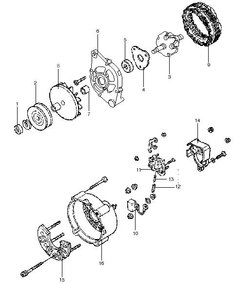
Disassembly
If the motor does not perform in accordance with published specifications, it may need to be disassembled for further testing of the components. Normally the cranking motor should be disassembled only so far as is necessary to make repairs or replace the defective parts. 1. Detach lead from solenoid terminal and remove thru-bolts. 2. Remove two screws and communtator end frame (brush assembly and bearing will remain on armature). 3. Remove armature from field frame and frame and shield from drive end frame assembly.
Caution:Magnets in frame have strong attraction to metal parts.
4. Use Proto Tools puller No.4041 or equivalent to pull bearing from armature.The bearing is a press fit over shaft. Note: Before removal lift brushes so spring rests against side of brush;this will prevent brush damage when brush assembly is pulled off of commutator.If springs are allowed to push brushes down when brush is moved off of commutator, the brush pigtail lead may be separated for the brush. 5. Slightly separate gear and drive assembly from drive end frame;use screwdriver to pry “plastic” shift lever off drive pins.Remove gear and drive from drive end frame. 6. To remove drive from shaft, remove collar, slide deep socket over shaft, tap socket to drive stop collar off snap ring.Remove snap ring and remove drive from shaft.
C AU TIO N! NO TE
-128-
Component Inspection and Repair
Brushes and Brush Holders
Inspect the brushes for wear.If they are worn excessively when compared with a new brush, they should be replaced.Make sure the brush holders are clean and the brushes are not binding in the holders. The full brush surface should ride on the commutator to give proper performance.Check by hand to ensure that the brush springs are giving firm contact between the brushes and commutator.If the springs are distorted or discolored, they should be replaced.
Armature
If commutator is rough or worn turn down only enough to clean the commutator surface.Do not undercut.
The armature should be checked for short circuits, opens, and grounds. 1. Short circuits are located by rotating the armature in a growler with a steel strip such as a hacksaw blade held on the armature.The steel strip will vibrate on the short circuit.Shorts between bars are sometimes produced by brush dust or copper between the bars. 2. Opens may be located by inspecting the points where the conductors are joined to the commutator for loose connections.Poor connections cause arcing and burning of the commutator.If commutator bars are black or discolored where windings are connected to bars, replace armature. 3. Grounds in the armature can be detected by the use of a test lamp.If the lamp lights when one test prod is placed on the commutator and the other test prod is place on the armature core or shaft, the armature is grounded.
Solenoid
With all leads disconnected from the solenoid, make test connections to the solenoid switch terminal and to ground, to check the hold-in winding.
-129-
Use the carbon pile across the battery to decrease the battery voltage to the value specified in GM Service Bulletin IS-188, and compare the ammeter reading with the specification.A high reading indicates a shorted or grounded hold-in winding, or grounded pullin winding, and a low reading excessive resistance. To check the pull-in winding, connect from the solenoid switch terminal (S), and to the solenoid motor (M) terminal. NO TE Note: If needed to reduce the voltage to the specified value, connect the carbon pile between the battery and “M”terminal as shown in the dashed lines instead of across the battery as shown in solid lines.If not needed, connect a jumper directly from the battery to the “M”terminal as shown in dashed lines.
C AU TIO N!
Caution:To prevent overheating,do not leave the pull-in winding energized more than 15 seconds. The current draw will decrease as the winding temperature increases.
Ammeter readings above the value specified in Service Bulletin IS-188 indicate shorted windings.A low reading indicates excessive resistance or an open.
Bearing Replacement and Lubrication
Install and lubricate bearings as follows.New prelubricated bearings normally do not require added lubricant. 1. Armature Commutator End Bearing a.Lift brushes up in holder with spring resting against side of brush. b.Place brush assembly over commutator. c.Press bearing inner race over shaft until inner race contacts stop shoulder. d.Bearing is sealed and requires no added lubrication. e.Lift springs to allow brushes to drop onto commutator. 2. Gear Bearing a.Press bearing to dimension shown.
b.Add lubricant P/N 10497186 to bearings if needed. 3. Drive End Housing Bearing a.Assemble bearings to dimension shown.
-130-
b.Add lubricant P/N 10497186 to bearings if needed. 4. Shaft Assembly Bearing a.Bearing and shaft are provided already assembled. b.Add lubricant P/N 10497186 if needed.
Starter Assembly
1. Place lubricant P/N 10497186 on inner gear teeth, planetary gears, and armature shaft gear teeth. 2. Assemble inner gear and drive over shaft. 3. Place stop collar and snap ring on shaft.Using two pliers, squeeze collar and stop collar over snap ring. 4. Assemble drive and shaft assembly into drive end frame.Use screwdriver to gently guide shift lever over shift collar pins on drive assembly. 5. Assemble shield, field frame and armature to drive end frame.
C AU TIO N!
Caution:Field frame magnets have strong attraction to armature.
6. Attach commutator end frame to brush assembly with two screw bolts. 7. Assemble thru-bolts. 8. After motor assembly, visually check pinions for proper movement to engaged, then disengaged, position by momentarily connecting battery to solenoid “S”terminal and motor frame.Two or three checks will ensure that shift lever is properly located over shift collar pins.C AU TIO N!
Caution:Secure motor in a vise,and keep hands away from pinion during test. Check Pinion Clearance
1. With motor lead disconnected from solenoid, connect 12 volt battery to solenoid “S”terminal and drive housing. 2. Momentarily flash a jumper lead from solenoid “M” terminal to drive housing.Pinion will shift into crank position.
3. Push pinion back to take up any movement, and check clearance between pinion and retainer with a feeler gauge.The clearance should be 0.010 and 0.160 in. 4. Clearance is necessary to prevent wear on drive collar during cranking.Clearance is not adjustable.
If not within limits, check for improper assembly or for worn parts.
-131-
Fuel System - Gasoline
Removal and Installation
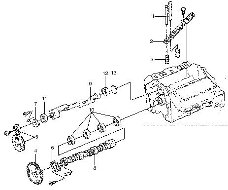
Removal steps
1.Nut 2.Washer - Spring 3.Washer 4.Seal - Oil 5.Hose 6.Bolt 7.Horn - Air 8.Bolt 9.Pipe - Fuel 10.Hose 11.Hose 12.Carburetor 13.Gasket 14.Nut 15.Hose 16.Hose 17.Adapter 18.Gasket - Adapter 19.Cable 20.Lever 21.Bracket 22.Motor - Step 23.Bracket - Motor
-132-
Fuel Pump and Fuel Hose
Removal and Installation
Precautions for Installation
•Install the fuel pump filter side bottom. •Put in the fuel hose securely to the nipple or joint, clamp it, and make sure that no fuel leaks. •Fasten the fuel hose securely to prevent it from being damaged by vibrations and touching any rotating or hot part.
-133-
Fuel Pump
Disassembly and Reassembly
Disassembly Steps
N N N
1.Pump cover 2.Magnet 3.Cover gasket 4.Filter 5.Filter gasket 6.Pump body
Main Point of DisassemblyC AU TIO N!
The transistorized fuel pump is of the totally enclosed type,except the filter side.Ordinary service work should be restricted to inspection and cleaning of the filter;never disassemble the fuel pump unnecessarily.Do not tamper with the fuel inlet elbow.Only items (2) to (5) can be replaced independently.
1.Remove the pump cover with a 17 mm (0.67 in.) wrench.Then take out the filter.Never impact upon the pump body during removal. N
N
N
-134-
Inspection
Checking and Cleaning the Filter
Check the filter for clogging and dirtiness.If necessary, clean or replace the filter.
Checking the Fuel Pump for Proper Function
Turn the ignition switch to ON and listen for clicks.If no click is made, connect the fuel pump directly to a 12volt power source and try listening for clicks.
Checking Delivery Flow
Check the pump delivery flow by using the method shown in the figure.Delivery flow of the pump is considered normal if 15-second delivery is 225 cm3 .
Main Point of Reassembly
Filter
1. Before installing the filter, check that the pump body side plunger valve is not clogged with dust. 2. Be sure to renew the filter gasket. 3. Fit the cleaned magnet to the cover without fail and install the cover securely.During trial run, check the cover and piping to see if no fuel leaks.
-135-
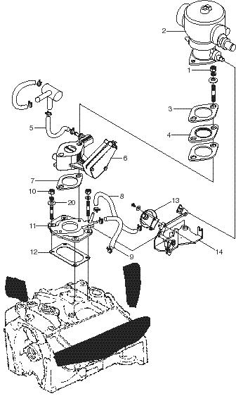
Fuel System - LP
Removal and Installation
N
N N
-136-
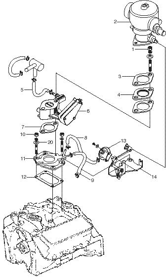
Removal steps
N
N
N
1.Nut 2.Carburetor Assy 3.Gasket 4.Spacer 5.Hose 6.Governor - Air 7.Gasket 8.Hose 9.Hose 10.Nut 11.Adapter 12.Gasket - Adapter 13.Actuator - Vacuum 14.Unit, Idle - Up
Maintenance Checks
At scheduled preventative maintenance increments:
1. Check coolant hoses for deterioration.Hardened hoses may crack or be subject to rupture, particularly if thermostats hotter than 160-170 degrees F are used, or if hoses are located adjacent to an exhaust manifold.Also check all vacuum hoses. 2. The fuel vapor hose is located between the vaporizer/regulator and the carburetor.Remove the hose and check for undue deterioration.
Particularly check the vapor outlet fitting from the regulator for tightness. 3. Use a soap/water solution or leak detector solution on all fittings while engine is running. 4. If starting and idling have been consistently satisfactory, it should be unnecessary to disassemble the carburetor air valve from the bowl.If inconsistent, remove the air valve cover, spring and air valve with the diaphragm.Check the gas-metering valve and gas jet for accumulation of foreign deposits or greasy substance, and clean both with a brush and kerosene or equivalent solvent as needed.
Check the air valve diaphragm for integrity and flexibility.Hold the diaphragm up against a strong light to check for small tears or pinholes.Normal life of the diaphragm and seat is 2,000 hours, barring excessive backfiring or similar abnormalities.When reinstalling the air-gas valve assembly in the bowl, mixer models CA100, CA125 and CA225 require reinstallation of the gas-metering valve in position with two gas valve slots opposing the gas inlet flow.This is for ideal air-fuel distribution. 5. With the carburetor air-gas valve and cover removed, it is a simple matter to check the converter and fuel lock for leaks.The following checks should indicate each component is operating properly. • Turn fuel on at the tank and check carburetor open gas jet for leakage.If the fuel lock and the converter are operating properly, no fuel will leak through. • Press the primer button on the front of the converter to open the gas regulator valve.A small amount of gas should pass through the jet as the system is emptied back to the fuel lock.If the fuel lock is operating properly, the gas flow will soon cease as soon as the fuel downstream of the fuel lock is exhausted. • Next remove the vacuum hose to the VFF30 fuel lock from the fitting at the source of vacuum. With the primer button depressed, apply vacuum to the fuel lock vacuum hose.Fuel should flow immediately and stop flowing when suction is relieved.
6. With consistent starting and idling, the vaporizer/ regulator need not be disassembled.If inconsistent, remove the regulator front cover and diaphragm assembly to check for oil and dirt deposits.If granules of foreign matter are embedded in the Viton rubber of the secondary valve, the valve and seat may be washed clean; however, it may be wise to replace the Viton valve for a perfect seal.These granules almost invariably enter the vaporizer in solution in the liquid propane and drop out as the fuel is vaporized, similar to salt water through a filter with deposits of salt left after evaporation of the water.It is seldom a sign of insufficient filtration.
Foreign matter and scale from the tank generally deposit in the filter when a new tank is installed. Welding scale and rust are frequently present in new tanks, and occasionally residual water from the hydrostatic pressure testing is still in the tank.
-137-
Impco Model VFF-30 Fuel Lock
Theory of Operations
•Impco vacuum fuel locks are normally closed. •They use air valve vacuum from the air fuel mixer to open the fuel lock. •If the engine stops or is turned off, engine vacuum dissipates and the fuel lockoff closes automatically.
This is a desirable safety feature. •When the engine is cranking or running air valve vacuum is transmitted from the mixer to the lockoff through a 3/16 in.vacuum hose. •The vacuum acts upon a diaphragm assembly.
Atmospheric pressure forces it inward against the valve operating lever. •As the valve operating lever is depressed it moves the valve operating pin. •As the valve operating pin moves it lifts the valve off of its seat. •This allows propane to flow through the lockoffs 10micron filter and on to the pressure regulator.
-138-
Vacuum Fuel Lock Service Procedures
•The Impco VFF30 vacuum fuel filter lockoff is fully field serviceable. •A repair kit is available (RK-VFF30) which includes all the wear parts necessary to rebuild the unit.
Each part is also available individually. •To test a unit for external leakage, apply an approved leak test solution to the entire outer surface and watch for leaks. •To test a unit for internal leakage remove the vacuum hose from the port marked VAC. •Apply an approved leak test agent to your finger tip and lightly place finger over port marked VAC. •Position your finger so that any LPG leaking internally and escaping out of the vacuum port will create small bubbles around your fingertip. •If bubbles are found, the pin and o-ring need replacing.
Vacuum Fuel Lock Installation Tips
•Lockoffs with filter elements should be positioned so that the filter can be changed as easily as possible. •Vacuum lockoffs should be positioned so that the atmospheric vent is not restricted. •Vacuum lockoffs should be positioned so that debris will not enter the atmospheric vent. •Vacuum lockoffs should be connected to air valve vacuum, not manifold vacuum.
-139-
Model J Regulator
Theory of Operation
This converter is a water-heated, two-stage vaporizer. Fuel enters the converter at tank pressure as a liquid and its pressure is reduced to 0.1 to 0.15 kgf/cm2 (1.4 to 2.1 psi) [10 to 15 kPa] within the primary or vaporizing chamber -- it is converted from liquid to a gas.Heat for vaporization is supplied form the engine cooling system.
Gas then passes through the secondary valve which is controlled by the secondary diaphragm and flows into the secondary chamber where it is drawn off through the gas outlet to the carburetor.
LPG Pressure Regulator Service Procedures
•lmpco pressure regulators have proven to be very reliable and require very little maintenance due to the robustness of their design and the small number of moving parts.Only periodic disassembly for the purpose of inspection and cleaning is required.The time interval between inspections varies with the quality of the fuel being used.A quick pressure test is all that is required to verify proper regulator operation.Repair kits are available from Impco, if required.These kits contain complete instructions and all wear parts necessary to rebuild an Impco pressure regulator. NO TE Use only genuine Impco replacement parts.
-140-
On-Vehicle Pressure Test
1. Shut off fuel supply at fuel storage container and run engine out of fuel. 2. Remove the primary test port plug. 3. Connect the ITK-1, 0-5 psi gauge to the primary test port. 4. Remove secondary test port plug. 5. Install the ITK-1, 0-10 inch wc (water column) gauge. 6. Slowly open fuel storage container valve. 7. Start engine. 8. Note gauge pressure readings. 9. Primary pressure should be approximately 1.5 psi. 10.Secondary pressure on regulators with a blue spring should be negative 1.5 w c. 11.Secondary pressure on regulators with an orange spring should be negative 0.5 w c. 12.Flip throttle several times then allow engine to idle. 13.Gauge readings will fluctuate and then should return to normal as engine idles and pressures stabilize. 14.If pressure readings differ from those stated above, the regulator should be disassembled and inspected as outlined below in "Regulator
Disassembly, Inspection, Cleaning and Assembly".
1. Shut off fuel supply at fuel storage container and run engine out of fuel. 2. Disconnect fuel inlet and outlet lines. 3. Drain cooling system or clamp hoses. 4. Remove regulator. 5. Disassemble regulator, 6. Clean primary and secondary valves with soap and warm water and inspect for wear.Replace if required. 7. Clean primary and secondary diaphragms with soap and warm water and inspect for wear. 8. Inspect primary diaphragm lever for straightness.
Replace if required. 9. Always replace the coolant chamber gasket. 10.Clean regulator castings with parts cleaning solvent and inspect.It is very rare for the castings to require replacement. 11.Reassemble regulator. 12.Use an anti-seize compound on screws. 13.Use an approved pipe sealant on fittings. 14.Bench test regulator.
Regulator Bench Test
1. Remove the primary test port plug. 2. Connect the ITK-1, 0-5 psi gauge to the primary test port. 3. Connect compressed air to the fuel inlet. 4. Pressurize the regulator. 5. Note reading on pressure gauge. 6. Gauge reading should be approximately 1.5 psi. 7. There should be no air escaping from the regulator outlet. 8. If air is escaping from the regulator outlet check the secondary diaphragm, secondary valve and seat. 9. Slowly push primer button several times and release. 10.Gauge will fluctuate but should return to approximately 1.5 psi.
LPG Pressure Regulator Installation Tips
1. Mount regulator below top of radiator.Air in the cooling system will seek the highest point.The regulator must not be the highest point.Air trapped in the regulator may cause it to freeze. 2. Mount regulator with fuel outlet pointing down.This allows for any heavy ends, such as butyl oil, that may be present in the fuel, to drain from the regulator.If any heavy ends are allowed to accumulate in the regulator they may interfere with the movement of the diaphragms. 3. Mount regulator to a solid surface.Fuel lines and coolant lines must not be used to support regulator. 4. Mount regulator as close as practical to the air fuel mixer.Since the regulator requires a negative pressure signal from the air fuel mixer to operate, mounting them close together will ensure short cranking time when starting the engine.
LP Regulator/Lockout - Removal and Replacement GF4OK Disassembly Steps
1. Turn off engine. 2. Run engine to clear LP system. 3. Drain coolant. 4. Remove battery. 5. Disconnect LP line at lockout. 6. Remove LP regulator/lockout assembly. 7. Remove water hoses from regulator. 8. Remove low pressure hose from regulator. 9. Remove vacuum hose from lockout. 10.Remove bracket from regulator/lockout. 11.Separate lockout from regulator.
-141-
Impco CA 100 Air Fuel Mixer
Air Valve Mixer Theory Of Operation
The air-gas valve mixer is mounted in the intake air stream above the throttle plates and is designed to create a slight pressure drop (negative pressure) as air is drawn through it in to the engine.This negative pressure signal is communicated to the upperside of the diaphragm through passages in the air-gas valve assembly (the air-gas valve assembly is mounted in the center of and supported by the diaphragm).
Atmospheric pressure acting on the underside of the diaphragm forces it upward against the metering spring.The metering spring is calibrated to generate about negative 6-inches of water column at idle and up to about negative 14-inches of water column at wide open throttle.The amount of negative pressure generated is a direct result of throttle position and the amount of air flowing through the mixer.As the diaphragm rises it lifts the tapered gas metering valve off of its seat and exposes the fuel outlet to the negative pressure generated within the mixer.This allows the negative pressure signal to travel to the secondary chamber of the pressure regulator and act upon the underside of the secondary diaphragm. Atmospheric pressure above the diaphragm forces it down against the secondary metering spring and opens the secondary valve allowing fuel to flow to the air-gas valve mixer.The tapered shape of the gasmetering valve is designed to maintain the correct air/fuel ratio over the entire operating range of the engine.
-142-
Model CA100 Carburetor Repair Kit
Installation Instructions
-143-
1.Screw 2.Cover 3.Spring, air valve 4.Screw *5.Plate, backup *6.Diaphragm *7.Ring, air valve *8.Air valve 9.Mixer body 10.Fitting 11.Screw, idle 12.Spring, idle screw 13.Plug 14.Gasket 15.Spacer 16.Adaptor 17.Air Valve Assembly
* Components included in the Repair Kit.
Model CA100 Carburetor Repair Kit Installation
1. Remove the air valve cover and retaining screws.
Place a chalk mark on the air valve diaphragm and the mixer body.This mark will allow correct positioning during reassembly.
2. Lift out and replace the air valve assembly in the mixer body.
3. Press the air valve down until it bottoms into the body. 4. Align the chalk mark on the air valve diaphragm with the chalk mark on the mixer body.
Reassemble the air valve cover and install retaining screws.
-144-
LPG Carburetor Adjustment Procedure CO/Exhaust Analyzer
1. Before starting make sure engine coolant and transmission oils are at full levels, and inching pedal is properly adjusted. 2. Turn idle mixture adjustment screw all the way “in” clockwise, then turn it “out”1-1/2 rotations. 3. Allow the engine and transmission temperature to warm up to operating temperature.Transmission temperature gauge should be just over first break line or higher. For console box without trans termperature gauge, warm truck up until engine coolant gauge is at block line or slightly above. 4. Adjust low idle to 750 ± 50 rpm using low idle adjustment screw.Then check engine timing and adjust as required to specification (8°BTDC). 5. Insert gas collection hose of emission analyzer into tail pipe of truck approximately 250mm (10in.)
Do not insert during warm up. 6. Idle adjustment with truck at low (750 ± 50 rpm) and in neutral, adjust the Idle Mixture Adjustment
Screw until the co-emission level is to a maximum
CO% of 0.8%. Turning the screw “in”will make the fuel mixture rich, higher CO level, and turning it “out”will make it lean, lower CO level. 7. Adjust the idle screw located on the idle up vacuum device so that it contacts the plunger. 8. Check high idle RPM to make sure it is not beyond 2700.If it is adjust the governor. 9. Power adjustment -- make sure truck is adequately secured, hold at converter stall full throttle, and adjust power valve until the CO emission level is a maximum of 1.0%.
There is a 5-10 second delay between making a power valve adjustment and picking up the effect on the analyzer.A slight change in power valve setting will NO TE produce a significant change in COlevel.Turning the power valve clockwise produces a rich mixture and higher CO levels.Turning it counterclockwise will produce a lean mixture and lower COlevels. 10.Remove gas collection hose. Governor Speed Adjustment Procedure 1. Set transmission in neutral position. 2. Press the accelerator pedal all the way to full open throttle. 3. Turn spring adjustment nut (A) clockwise to increase rpm.Turn nut counter clockwise to decrease rpm. 4. When turning nut, hold the adjusting screw (A1). The adjusting screw is only used to adjust hunting.
Adjustment for Eliminating Hunting:
1. Set transmission in neutral position. 2. Press the accelerator pedal all the way. 3. Gradually turn the adjusting screw (B) clockwise until the engine no longer hunts.
NO TE
NO TEFuel System - LP
-145-
ServiceManual
GM 4.3L Gasoline Engine
Pub.No.99789-84100

99789-84100 Copyright ' 2000 by MCFA. All Rights Reserved. CATERPILLAR and CAT are registered trademarks of Caterpillar Inc. Printed in the U.S.A.