7 minute read
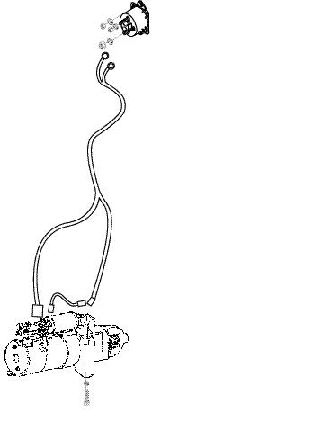
Starter Motor


Ignition System - Distributor
Removal and Installation
Advertisement
13
14
15
16
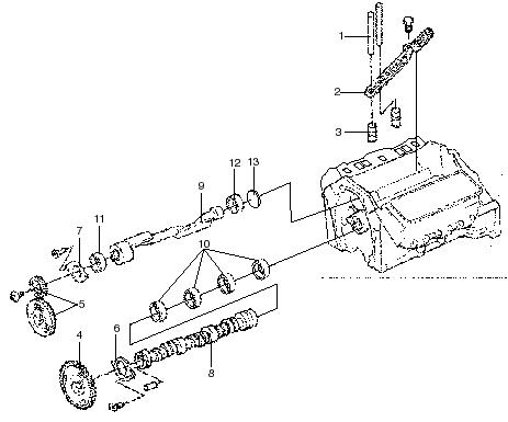
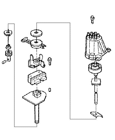
Removal steps
1.Screw 2.Distributor Cap 3.Rotor 4.Shaft Assembly 5.Retainer 6.Shield 7.Sensing Coil 8.Pole, Stationary 9.Screw (4) 10.EST Module 11.Pin 12.Housing 13.Tab Washer 14.Washer 15.Gear 16.Roll Pin 6
7
8
9
10
11
12
-116-
1
2
3
4
5
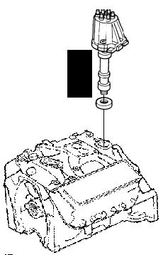
C Distributor Removal
Position the engine on TDC (top dead center) #1 compression stroke before removing the distributor. This will be a good reference point when reinstalling the distributor in the engine.
Before starting removal steps of coil or distributor, disconnect the negative battery cable 1. Remove all wires from the distributor, spark plug, coil and harness wires. 2. Remove the two screws on the distributor cap and remove the cap. 3. Place a mark on the distributor housing where the rotor is pointing.Then put a corresponding mark on the distributor housing and then on the engine.
This will be a known starting point for reassembly. 4. Remove the bolt and clamp that hold the distributor in the engine and then remove the distributor.
C AU TIO N! NO TE
34403
Distributor Disassembly
1. Remove the rotor from the shaft by lifting straight from the end of the shaft. 2. Put an alignment mark on the shaft and gear for correct installation.Use a small punch to remove the roll pin as shown.Do not damage the shaft or gear.
3. Remove the gear, washer, and tab washer. 4. Remove the shaft with the pole piece and plate from the housing.C AU TIO N!
When the distributor is disassembled,the retainer must be replaced.NEVER use an old retainer.
5. Remove the retainer from the housing using a screwdriver.Remove the shield. 6. Remove the sensing coil connector from the module.Lift the locking tab with a screwdriver. Remove the sensing coil. 7. Remove the two screws that fasten the module to the plate.Remove the module. Distributor AssemblyNO TE A small amount silicon grease is supplied with each replacement module.If silicon grease is needed, use the 5P8937 Heat Sink Compound.
1. Completely cover the bottom of the module with a thin layer of 5P8937 Heat Sink Compound or an equivalent compound for heat transfer.
-117-
Ignition System and DistributorC AU TIO N!
Make sure the bottom of themodule is completely covered with a thin layer of 5P8937 heat sink compound.If the silicon grease is not correctly applied,the module can be damaged by heat.
2. Install themodule on the housing using the two screws. 3. Install the sensing coil on the shaft assembly.
Make sure the locking tab is in the correct position. 4. Install the shield on the sensing coil and the new retainer to fasten the shield and coil. 5. Install the shaft assembly into the housing.Install the tab washer, the washer, and the gear on the shaft.Align the marks on the gear and the shaft for correct alignment. 6. Install the roll pin into the gear to lock the gear and shaft together.Rotate the shaft to make sure the teeth on the shaft assembly do not touch the pole piece.
A Spark Plug Wires and Coil Wire Removal
1. Remove all wires by the boots, do not pull on the wires.Note the arrangement of the wires before removing. 2. Check all wires and boot ends for cracks, burnt or
hard rubber.Inspect wires for broken insulation or chafing. 3. Inspect wire ends and boots for tight fit on and over spark plugs and distributor.
A Spark Plug Wires and Coil Wire Installation
1. Measure each spark plug wire resistance. 2. Measure coil wire resistance.
3. Install the spark plug wires on the distributor cap as shown. 4. Install the wires on spark plugs following the firing order shown.Firing Order 165432
-118-
5. Install the coil wire on the distributor and then the coil. 6. Make sure all wires fit tightly around the distributor cap and spark plugs.Install each wire in the supporting clips and make sure all wires are kept clear of the exhaust manifold and heat shields.
B Coil Installation and Testing
1. Ignition coil testing, open and short circuits, and coil can be tested on or off the engine. 2. Make sure all test points are clean from paint, dirt, grease and oil before testing.Disconnect all wires from the coil before testing.
3. Ignition coil testing. a)Connect a volt/ohmmeter as shown in step 1. Set the meter on ohms scale.If the meter indication is infinity or open circuit, the coil is good. b)Connect the meter as shown in step 2.Set the meter on the ohms scale.If the meter indication is < (less than) 1 ohm, the coil is good. c)Connect the meter as shown in step 3.Set the meter on the ohms scale, 20k.If the meter indication shows infinity or open circuit the coil should be replaced. 4. Install the coil to the mounting bracket and connect the distributor wire, coil wire and engine wiring harness.
B Coil RemovalC AU TIO N!
Before starting removal steps of coil or distributor, disconnect the negative battery cable.
1. Remove coil mounting bolts and coil from the bracket. 2. Remove all wires connected to the coil. 3. Check coil for damage or broken connectors.
Ignition Sensing Coil TestNO TE
The following procedure will check the resistance of the sensing coil for the ignition module inside the distributor.The distributor can be left on the engine or removed for this test.
1. Connect an ohmmeter to either sensing coil connection and the housing as shown in step 1.If the reading is not infinity or open, replace the sensing coil.
-119-
2. Connect an ohmmeter to both connectors of the sensing coil as shown in step 2.Move the connectors at the sensing coil and at the connector to find any open circuits that are not constant.The ohmmeter will correctly indicate 500 to 1500 ohms.If the indication is not constant or is not within the resistance range, replace the sensing coil.
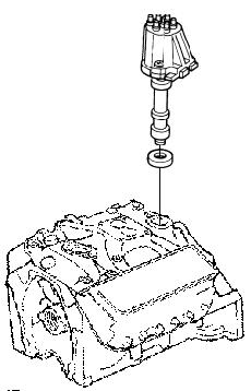
C Distributor Installation
1. Use the following steps to install: a.Align the rotor with the mark on the distributor housing made during removal. b.Align the mark on the distributor housing and the engine made during removal. c.Install a new gasket between distributor housing and the engine. d.Install the distributor in the engine. Hint:Make sure both the rotor and distributor housing marks are correctly aligned before going to the next step.Also make sure that the distributor is fully inserted in the engine. 2. Install the clamp and the bolt.Tighten the bolt enough to hold the distributor in position, but do not tighten completely. 3. If the distributor cap is not being replaced, inspect the cap for carbon, cracks or small holes.Replace the distributor cap if it is dirty or damaged.Install the distributor cap on the distributor.Install the high voltage wires in their correct positions. 4. Install the coil lead wire and engine harness connector to the distributor. 5. Reconnect the negative battery cable.
-120-
Ignition Timing
NO TE
Before trying to start the engine, make sure the distributor is installed correctly, and all high voltage wires are connected and installed correctly on the coil and distributor.
1. Locate the correct timing mark, Gasoline or LP (0°
BTDC Gasoline)[ 8° BTDC L.P.G.] on the balancer pulley and front engine cover.
2. Connect an inductive type timing light on No.1 spark plug wire. 3. Start the engine.The engine does not start rotating the distributor clockwise or counterclockwise until the engine starts.If engine still will not start, go back to the EST Distributor
Installation section.Once the engine is running smoothly let it idle until the engine reaches normal operational temperature. 4. With engine running at an idle and warm, unplug the 4-wire connector on the distributor (gas only) and connect the timing shunt tool MCF-1094 to the 4-pin connector on the side of the distributor.Next connect the alligator clip lead from the tool to the positive (+) side of the 12 volt battery with the engine running.This will cause the engine to slow down and default the distributor to basic timing.
Read the timing off the balancer pulley with the timing light.If timing is showing something other than what is shown in the engine specifications (gas or LP) section it must be adjusted.Loosen the distributor and rotate it until the correct reading is obtained.Retighten the distributor, hold down clamp, and recheck timing again.
C AU TIO N!
Do not shut engine off with the 12 volt lead connected to the battery or restart the engine with the timing shunt connected.Connecting the timing shunt to 12 volt + battery with the engine not running can cause damage to the ECU or the EST module.
-121-