7 minute read
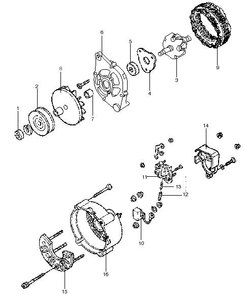
Oil Pan,Pump and Filter

MCF-1090 (J 38606)
9. Remove the valve keys. 10.Carefully release the valve spring tension. 11.Remove the MCF-1089 (J 5892-D) or MCF-1090 (J 38606). 12.Remove the cap, rotator, and spring. 13.Remove the valve seal.
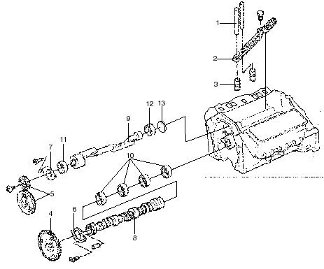
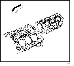
Cylinder Head Removal
1. Remove the intake manifold. 2. Remove the exhaust manifold. 3. Remove the following components from the left cylinder head: • The electrical connector at the coolant temperature sensor • Spark plugs
4. Remove the alternator and bracket from the right cylinder head. 5. Remove valve rocker arm cover.
-42-
6. Remove valve arm and push rods.
7. Remove cyclinder head. 8. Remove the gasket.


-43-
Cylinder Head Disassembly and Assembly
Disassembly Tools Required
• MCF-1069 (J 8062) Valve Spring Compressor 1. Use MCF-1069 (J 8062) to compress the valve springs.
MCF-1069 (J 8062)
NO TE
2. Remove the valve stem keys (1). 3. Remove the cap (2) from the valve (5 or 6). 4. Remove the valve spring (4). 5. Remove the valve stem oil seal (3). 6. Remove the valve (5 or 6).Place the valves in a rack in the proper sequence so you can install them in the same order.
Assembly Tools Required
• MCF-1069 (J 8062) Valve Spring Compressor • MCF-1087 (J 42073) Valve Stem Oil Seal Installer 1. Clean the valve spring seat area. 2. Install the valve into the proper port.
Important: In order for tool MCF-1087 (J 42073) to work properly, the valve is installed into the cylinder head.
3. Lubricate guide and valve stem oil seal (3) with clean engine oil.
Important: Install the valve stem oil seal (3) onto the valve stem (5 or 6).Push the seal down until the seal contacts the valve guide (2).
4. Valve stem oil seal alignment onto the valve guide is critical.
NO TE NO TE
MCF-1087 (J 42073)
-44-
5. Place the MCF-1087 (J 42073) over the valve stem and oil seal.Lightly tap on the MCF-1087 (J 42073) until the tool bottoms out against the valve spring seat. 6. Install the valve spring (4).NO TE Important: A correctly installed seal should not bottom against the valve guide.There should be a 1-2 mm (0.03937-0.07874 in.) gap (2) between the bottom edge of the seal (5) and the valve guide (4). 10.Measure the valve spring installed height from the valve spring seat to the locating surface on the cap.
MCF-1069 (J 8062)
7. Install the cap (2) on the valve stem. 8. Use the MCF-1069 (J 8062) to compress the valve spring. 9. Install the valve stem keys (1). • Use grease to hold the keys in place while disconnecting the MCF-1069 (J 8062). • Make sure the keys seat properly in the upper groove of the valve stem. • Tap the end of the stem with a plastic-faced hammer to seat the keys if necessary.
Cylinder Head Clean and Inspect
Tools Required
• MCF-1082 (J 9666) Valve Spring Tester • MCF-1067 (J 8001) Dial Indicator Set 1. Use the MCF-1092 (J 8089) to clean the carbon from the combustion chambers and the valve parts.Be careful not to scuff the chamber.
MCF-1092 (J 8089)
-45-
2. Clean the following areas. • The carbon and the sludge from the valve pushrods and the valve rocker arms • The valve stems and heads on a buffing wheel • The cylinder head and engine block gasket surfaces • The bolt hole threads in the cylinder heads and the engine block 3. Inspect the following areas. • The cylinder head for cracks in the exhaust ports and combustion chambers • The cylinder head for external cracks in the water chamber • The valves for burned heads, cracked faces, or damaged stems • The valve springs for squareness 4. Use the MCF-1082 (J 9666) to measure the valve spring. • Replace the intake valve spring if the spring tension is less than 360 N (81 lb) at 45.2 mm (1.78 in.). • Replace the exhaust valve spring if the spring tension is less than 425 N (96 lb) at 45.2 mm (1.78 in.). 5. Measure the valve stem-to-bore clearance. • Excessive valve stem-to-bore clearance will cause excessive oil consumption and may cause a valve to break.Insufficient clearance will result in noisy and sticky functioning of the valve and will disturb the engine assembly smoothness. • Clamp the MCF-1067 (J 8001) on the exhaust port side of the cylinder head. • Locate the indicator so the movement of the valve stem from side to side (crosswise to the cylinder head) will cause a direct movement of the indicator stem.The indicator stem must contact the side of the valve stem just above the valve guide. • Drop the valve head about 1.6 mm (0.064 in.) off the valve seat. • Use light pressure when moving the valve stem from side to side to obtain clearance reading.
MCF-1082 (J 9666)
MCF-1067 (J 8001)
-46-
Valve Guide Reaming/Valve and Seat Grinding
1. Ream the valve guides for oversize valves if the clearance exceeds the specifications. 2. Ream the valve guide bores for the oversize valves as necessary. 3. Reconditioning the valve seats is very important.
Recondition valve seat after reaming the valve guide bores or installing the new valve guides. • The valves must seat perfectly for the engine to deliver optimum power and performance. • Cooling the valve heads is another important factor.Good contact between each valve and its seat in the cylinder head is necessary to ensure that the heat in the valve head is properly carried away. • Regardless of what type of equipment is used, it is essential the valve guide bores are free from carbon or dirt to ensure the proper centering of the pilot in the guide.The valve seats should be concentric to within 0.79 mm (0.031 in.) total indicator reading. • Reface pitted valves on a valve refacing machine to ensure the correct relationship between the head and the stem.Replace the valve if the stem is warped, or if the stem shows signs of excessive wear.Replace the valve if the edge of the head is less than 0.79 mm (0.031 in.) thick after grinding. • Several different types of equipment are available for reconditioning valves and valve seats.Use the manufacturer recommendations of equipment to attain the proper results
Valve Stem Oil Seal and Valve Spring Installation
Tools Required
• J 23590 Spark Plug Adapter • MCF-1089 (J 5892-D) Valve Spring Compressor • MCF-1090 (J 38606) Valve Spring Compressor 1. Install the new valve seal (3) over the valve stem and set it against the head. 2. Install the cap (2), rotator, and spring (4). 3. Use the MCF-1089 (J 5892-D).
4. Use the MCF-1090 (J 38606) if clearance does not permit use of MCF-1089 (J 5892-D).
MCF-1089 (J 5892-D)
MCF-1090 (J 38606)
-47-
5. Install the valve keys (1).Use grease to hold the valve keys in place.
6. Carefully release the valve spring pressure, making sure the valve keys stay in place. 7. Remove the J 23590, MCF-1089 (J 5892-D) or
MCF-1090 (J 38606). 8. Install the spark plugs.
9. Install the valve rocker arms. 10.Install the valve rocker arm cover.
Valve Lifter Installation
1.Install the valve lifters. 2.Install the retainer.
Valve Rocker Arm and Push Rod Installation
1. Install the pushrod, rocker arm with ball and nut.
Refer to Valve Rocker Arm and Push Rod
Removal. 2. Replace the rocker arm cover. • For the right side of the truck, refer to Valve Rocker Arm Cover Replacement (Left). • For the left side of the truck, refer to Valve Rocker Arm Cover Replacement (Right).
-48-
Cylinder Head Installation
1. Install the cylinder head.

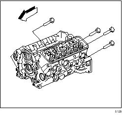
2. Torque the cylinder head bolts in sequence on the first pass.
Tightening torque 3.05 Kgf•m (22lbf•ft) [30 N•m] for cylinder head bolts
3. Use MCF-1074 (J 36660)Electronic Torque Angle
Meter, in order to tighten the cylinder head bolts in sequence on the final pass.
Tighten on the long bolts (1, 4, 5, 8, and 9) on the final pass in sequence to 75 degrees. Tighten the medium bolts (12 and 13) on the final pass in sequence to 65 degrees. Tighten the short bolts (2, 3, 6, 7, 10, and 11) on the final pass in sequence to 55 degrees. 4. Install the pushrods. 5. Install the valve rocker arm cover. 6. Install the oil level indicator tube. 7. Install the starter relay. 8. Install the crankcase vent tube. 9. Connect the spark plug wires to the spark plugs. 10.Connect the negative battery cable. 11.Install the following components to the left cylinder head. • The electrical connector at the coolant temperature sensor 12.Install the alternator and bracket to the right cylinder head. 13.Install the exhaust manifold. 14.Install the intake manifold.
-49-
Valve Rocker Arm Cover Left Installation
1. Install the valve rocker arm cover.
2. Install PCV valve and tube. 3. Connect the spark plug wires to the spark plugs. 4. Install the ignition coil. 5. Connect the negative battery cable.
-50-