3 minute read
Diagnostic Information and Procedures

Engine Replacement Removal ProcedureNO TE
If the engine is damaged internally and a new engine assembly is installed in the machine, ensure that all foreign material is flushed out of the cooling system.It is necessary to flush out the oil cooler system.Failure to rid the oil cooler system of debris can result in engine damage.
1. Disconnect battery. 2. Raise the machine and support with stands. 3. Drain fluids and oil filter removal a.Remove the oil pan drain plug, and allow oil to drain. b.Remove the oil filter. c.Remove both coolant drain plugs and allow coolant to drain. 4. Disconnect the exhaust pipe from the exhaust manifolds. 5. Disconnect the following items: • The wiring harnesses • The throttle cable • The fuel lines 6. Support engine using appropriate sling and hoist.
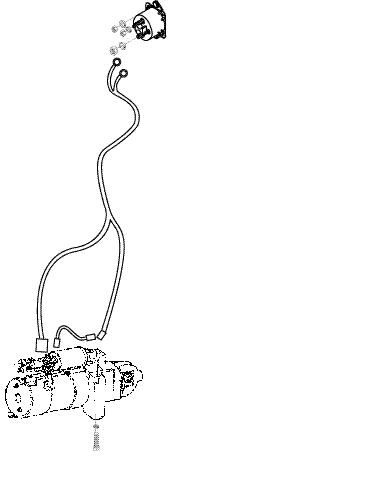
Use existing lift eyes. 7. Disconnect the fuel line and fuel line clamp. 8. Remove the starter.Refer to Engine Electrical. 9. Disconnect the torque convertor bolts from the flywheel. 10.Remove the oil filter. 11.Support the transmission with a jack. 12.Remove the transmission engine bolts. 13.Remove the front engine mount bolts. 14.Remove the distributor. 15.Use the engine lifting device to remove the engine from the machine.
Installation Procedure NO TE
If the engine is damaged internally and a new engine assembly is installed in the machine, ensure that all foreign material is flushed out of the cooling system.It is necessary to flush out the oil cooler system.Failure to rid the oil cooler system of debris can result in engine damage.
1. Raise the machine. 2. Install the engine into the machine. 3. Install the left upper transmission to engine bolt. 4. Install the front engine mounts. 5. Install the distributor. 6. Install the following items: • The wiring harnesses • The vacuum lines • The throttle cable • The fuel lines 7. Install torque convertor to flywheel bolts. 8. Install the remaining transmission to engine bolts. 9. Install the oil filter. 10.Install the pump drive shaft. 11.Install the starter.Refer to Engine Electrical. 12.Connect the fuel line and fuel line clamp. 13.Connect the exhaust pipe to the exhaust manifolds. 14.Lower the machine. 15.Fill the crankcase with oil. 16.Fill radiator with coolant. 17.Connect battery.
-13-
Engine Specifications - Gas and LP
Application Specification
Engine Engine Model GM 4.3L Manufacturer General Motors
Type Gasoline Cooling System Water Cooled No.of Cylinders - Arrangement 6 - 90° V No.of Stroke 4
Type of Combustion Chamber Semi - Spherical Valve Arrangement Overhead Type of Cylinder Liner Integral Cylinder Bore x Stroke, mm (in) 101.6x88.39 (4.00x3.48) Displacement, cc (cu in) 4293 (262) Compression Ratio 9.2:1 Rated Output, PS/rpm 94/ 2450 Rated Torque, kgf -m/rpm 31.0/1200 Min.rpm 750 ± 50 Max.rpm 2650-2700 Dimensions (LxWxH), mm 710x620x740 (28x24.5x29) Weight, kg (lbs) 260 (572) Installation Position Rear
Ignition Spark Firing Order 1-6-5-4-3-2 Initial Ignition Timing BTDC deg 0° Gasoline, 8° L.P.G. Rotation (View From Pulley) CW Voltage for Electric System 12 V
-14-
Engine Specifications - Gas and LP,continued
Application Specification
Ignition System HEI or EST Ignition Coil - Type Mold Manufacturer AC Delco
Distributor - Type Pointless Manufacturer AC Delco
Type of Spark Advance Control Internal Solid State Circuit Spark Plug - Model AC #41 - 932 Manufacturer AC Delco
Size, mm 14 (0.55) Gap, mm (in) 1.52 (.060) Fuel System GAS LP Carburetor/ Mixer-Type IFZ CA100 Manufacturer AISAN Kogyo Co. IMPCO Governor - Type Electronic Pneumatic Manufacturer
Mitsubishi Heavy Industries AISAN Kogyo Co.
Fuel Pump - Type Electromagnetic –Manufacturer Jidosha Kiki –
Engine Lubrication System Type Pressure Feed Oil Pump Gear Pump Oil Filter Paper Element Oil Cooler Oil to Water Type Refill Capacity, Liter (Quart) Oil Pan 4.0 (4.2) Oil Filter and Cooler 0.7 (0.8) Total 4.7 (5.0)
-15-