7 minute read
Conveyor chain ........................................................... 5


Conveyor chain
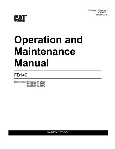
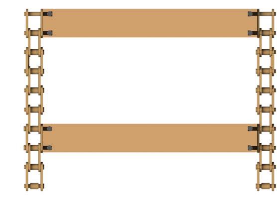
The conveyor chain (Fig. 74) is made up of one basic chain assembly which repeats sequentially along the entire chain loop. As soon as any component of the conveyor chain is worn the component or complete conveyor chain assembly must be replaced.
Each conveyor chain section consists of the following main components:
■ 6 link chain section
■ flight bar
■ spiral pin
Fig. 74: Conveyor chain main components

Spiral pin
6 link chain section
Flight bar
Measure Chain for Elongation
One of the most important areas in the evaluation of chain wear is the elongation of the chain. This is obtainable in the field and does not require chain disassembly or return to manufacturer for analysis.
To measure a chain for elongation:
The selected strand must be under some load to pull out internal clearances and must be supported, if necessary, to insure the chain lies in a straight line.
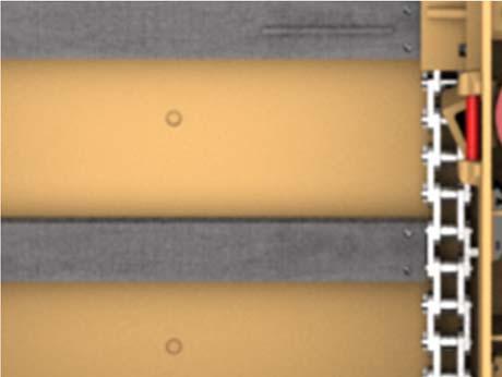
The ideal selected strand should include 20 pitches, to ensure a result representative of the entirety of the chain. If less are measured, the absolute minimum of four pitches is considered acceptable (more pitches measured, provides a higher resolution of elongation). Always use
an even number of pitches for straight sidebar chain.
Use any reasonably accurate measuring device (steel ruler, calipers, tape measure, etc.).
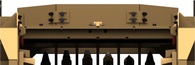
Determine the distance from a spot on the first pitch to the same spot on the last pitch. The edge of the pin head is usually a good spot to measure (see Fig. 75).
Fig. 75: Chain elongation measurement
Replacement chain should be order at approximately 2.6% elongation and replaced at approximately 3% elongation. It is highly recommend-
ed that the head shaft sprockets be changed at the same time as a new chain is installed to obtain maximum chain life.
Table 4 lists chain order and replacement values.
Table 4: Chain elongation values
Chain Pitch Baseline Length (20 pitches)
Order Length (approximately 2.6%) (20 pitches)
Replacement Length (approximately 3%) (20 pitches)
3.500 70 inches 71 13/16 inches 72 1/8 inches 3.750 75 inches 76 15/16 inches 77 1/4 inches
How to assemble the conveyor chain sections
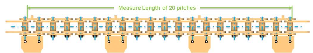
To assemble the conveyor chain sections proceed as follows (Fig. 76):
1. Lay conveyor chain sections on a clean flat surface.
2. Insert connector pins through flight end and align holes in spiral pin with holes in flight bar.
3. Insert spiral pin.
4. Drive spiral pin in with a hammer and punch. Ensure that spiral pin is recessed on both sides of flight bar.
5. Repeat the previous assembly instructions until the complete chain has been assembled.
Fig: 76: Conveyor chain assembly
6 link chain section
Extended pin connecting link Spiral pin (4)
Block link assembly Flight bar
Side bar
How to remove the conveyor chain assembly
To remove the conveyor chain assembly proceed as follows: 1. Release tension on the conveyor chain. (See Conveyor chain adjustment in this chapter).
2. At the chain disassembly/assembly point, raise the chain a minimum of 3” high and block it under the flight.
Note: There are notches in the frame on both sides of the conveyor deck. The notches are to provide access to the conveyor chain during disassembly and assembly. This is the chain disassembly/assembly point.
3. Separate conveyor chain by removing spiral pins and connecting links in one section of the chain.
4. Connect a pulling device (e.g. winch or lifting tackle with adequate load limit), or the new conveyor chain, to either end of the old conveyor chain and slowly pull the old conveyor chain completely out of the machine.
WARNING! When using a pulling device (e.g. winch or lifting tackle with adequate load limit) for pulling the conveyor chain, the connection could fracture under the load. You could be seriously injured or killed by the recoiling chain or cable. Use only approved lifting equipment for connecting pulling devices to the conveyor chain.
How to install the conveyor chain assembly
To install the conveyor chain assembly proceed as follows:
1. Check to ensure that the conveyor tail shaft is completely retracted. If not retracted, see Conveyor chain adjustment in this chapter.
2. If the old conveyor chain was not used to install the new conveyor chain, then run a cable or pull rope with an adequate load limit through the bottom conveyor pan and connect to the conveyor chain.
3. Connect an additional pulling or lifting device (e.g. winch or lifting tackle with adequate load limit) to the other end of the cable or pull rope and slowly pull the new conveyor chain completely through the bottom conveyor pan.
IMPORTANT! If old conveyor chain is still on machine, installation can be facilitated by connecting the new conveyor chain to the old conveyor chain via the chain connectors and pulling it through the bottom conveyor pan.
4. Fold conveyor chain back over the tail shaft and drive shaft and slowly pull the chain along the conveyor ensuring that the chain is under the chain hold downs.
5. Ensure that the chain is properly meshed with the sprockets on the head and rollers on the tailshaft.
6. Connect conveyor chain (see How to assemble the conveyor chain sections in this chapter for proper connection).
7. Adjust tension on the conveyor chain (see Conveyor chain adjustment procedure in this chapter.
8. With machine running, visually inspect tail shaft to ensure that the conveyor chain is properly engaged with the tailshaft rollers.
TAC monitor for conveyor speed sensor
To replace the conveyor speed sensor TAC monitor:
Note: The machine shipped from the factory with TAC monitor model 22-8100. This model is obsolete and has been replaced with model 220 -8100. All instructions are for the installation of 220-8100.
1. Disconnect power from the machine following all applicable lockout/tagout regulations.
2. Open the control panel enclosure and locate the existing TAC monitor, mounted on the front side of the swing panel (Fig. 77).
Fig. 77: TAC monitor location (typical)
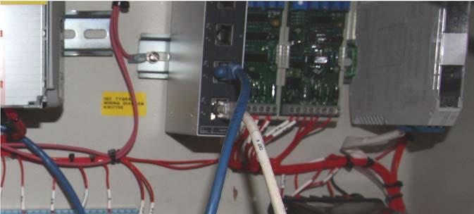
TAC monitor
3. Disconnect the existing monitor and remove.
4. Mount the new monitor on the swing panel. Connect the wires as shown in Table 5. Note: the connections on the model 22-8100
TAC monitor do not match the connections on the new monitor.
Table 5 is for the 220-8100 model only.
Table 5: Terminal connections (220-8100 model)
Terminal Connection
Front
1 No connection
2 No connection
3 4-20mA Output - Positive (+) 4 4-20mA Output - Common (1) 5 No connection
6 No connection
7 Sensor Input (+) 8 Sensor Input Common (-)
9 No connection
Back
10 No connection
11 No connection
12 No connection
13 No connection
14 No connection
15 AC Input (N) 16 AC Input (H)
5. Restore power to the machine.
Setup and display indicators
When power is applied to the TAC monitor, the display will should show the following:
000 RPM - displays the actual value from the remote speed sensor. If “Line Open” is displayed, check the 4-20mA line. The maximum line resistance is 0-500 ohm.
10-XXXX RPM - displays the current speed range of the TAC monitor (10 to XXXX RPM). The display should read 10-100 RPM. If the correct range is not selected, chose the correct range as follows:
1. Press and hold the “SET” button for approximately 4 seconds. The display should now show models from 100 RPM top range to 6000
RPM top range.
2. Using the arrow key, highlight the 100 RPM top range model from the list.
3. With the 100 RPM top range model selected, press and hold the
“SET” button for approximately 4 seconds. The display will now change back to normal operation with eh new RPM range shown on the bottom of the screen.
Note: If a selection is not made with approximately 10 seconds, the display will return to normal operation and will keep the existing model speed range.