2 minute read
Main pump adjustments ................................................ 5


There are two pumps on the machine: an open loop, load sense pump and a piggyback fixed displacement gear pump. The open loop, load sense pump powers all hydraulic functions while the piggyback fixed displacement gear pump supplies cooling flow to the cases of the main pump and the conveyor drive motor and drives the heat exchanger fan motor, if equipped. There are no adjustments on the gear pump.
Main pump adjustments
Margin pressure
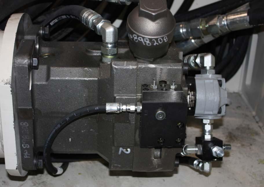
The adjustment of the load sense margin pressure is located on the control block at the top rear of the pump. It is the adjusting screw located at the front of the block.
To adjust the margin pressure on the main pump:
1. Tee a multi-gauge into the system pressure line.
2. With no functions active, the margin pressure should read 30 bar (435 psi). If adjustment is necessary:
a. Locate the margin pressure cartridge (Fig. 66).
b. Loosen the hex nut that holds the adjustment stem in place.
c. Turn the stem clockwise (in) to increase pressure or counterclockwise (out) to decrease pressure.
d. Once the desired pressure, 30 bar (435 psi), is obtained, tighten the hex nut while holding the adjustment stem in place.
e. After the hex nut is tight, recheck the pressure to ensure the adjustment stem did not move. If necessary, readjust.
Pressure compensator
The adjustment of the pressure compensator setting is located on the control block at the top rear of the pump. It is the adjusting screw located at the rear of the block. The pressure compensator must be adjusted while the pump is “loaded”. This is best accomplished with the conveyor function engaged.
To adjust the pressure compensator setting:
1. Tee a multi-gauge into the system pressure line.
2. Adjust the main relief valve to 370 bar (5,365 psi) (see Main relief adjustment procedure in this section).
3. Zero out the margin pressure adjustment by turning the adjustment stem (Fig. 66) clockwise (in) all the way. This system will now be a pressure compensated system and will maintain system pressure at all times. The pressure should now read 350 bar (5,000 psi). If adjustment is necessary:
a. Loosen the hex nut that holds the adjustment stem in place.
b. Turn the stem clockwise (in) to increase pressure or counterclockwise (out) to decrease pressure.
c. While holding the adjustment stem in place, tighten the hex nut.
4. Adjust the main relief valve to 370 bar (5,365 psi).
5. Once the pressure compensator is set, reset the margin pressure adjustment to 30 bar (435 psi) (see Margin pressure adjustment procedure in this section).
Fig. 66: Pump
Pressure compensator adjustment Margin pressure adjustment