1 minute read
Conveyor chain adjustment .......................................... 5


Conveyor chain adjustment
The conveyor chain is a complete assembly and should be checked for correct tension at regular intervals.
NOTICE! The following adjustment procedure for conveyor chain take-up must be performed on both right and left hand sides of the conveyor.
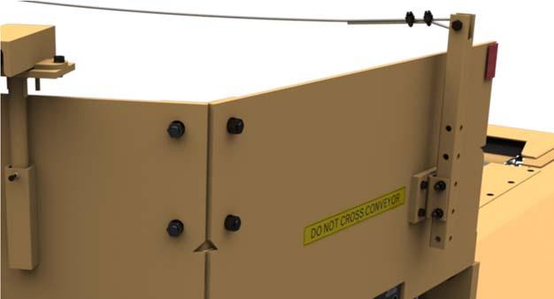
To adjust tension on the conveyor chain with the take-up cylinders proceed as follows (Fig. 62):
1. Close the needle valve on manifold assembly securely.
2. Attach a grease gun to the grease fitting located on the manifold and apply grease until the required chain tension is obtained.
Sight across the bottom of the head shaft sprocket. The chain should sag approximately two inches below the bottom of the head shaft sprocket.
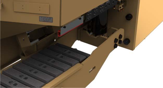
3. After tensioning the conveyor chain, locate the tailshaft take-up grease cylinders to the inside of the crawler tilt cylinders and remove the hardware that secures the shim pack onto the grease cylinder rod.
4. Insert shims over cylinder rod to fill the gap between the cylinder and the take-up push rod. Note the thickness and number of shims so that the other side is shimmed to the same length.
NOTICE! Make certain that the same amounts of shims are used on both sides of the conveyor to prevent chain from stretching unevenly. Incorrect tension or adjustment can cause premature wear of sprockets and chain. Measure the exposed rod length on the grease take-up cylinders and make sure they are within 1/4” of each other.
5. Replace retainers.
6. Release pressure on the take-up cylinders by opening the top valve to vent grease. After grease has vented, close valve.
WARNING! Due to grease cylinders being under high pressure, do not stand in direct line of grease fitting or needle valve when releasing pressure. You could be seriously injured from high pressure grease.
7. Store any unused shims inside the shim storage boxes.
Fig. 62: Conveyor chain adjustment

Needle valve (2)
Grease fitting (2)
Shim storage (2)
Grease take-up cylinder (2)