3 minute read
Electrical system ................................................................. 5


Electrical system
The following pages contain a brief description of the major electrical components and assemblies that are on the feeder breaker.
The machine receives electrical power through a heavy-duty trailing cable. Be sure that the box connector is correctly identified and is securely connected; also check that the cable entrance is in good mechanical condition. Walk along the trailing cable from the power center to the feeder breaker and check the condition of the trailing cable. Give special attention to points most apt to cause damage, such as corners, intersections, and where cable may be run over by moving equipment. Never use trailing cable with exposed wires or splices which heat up or spark under load.
WARNING! This section is intended only to familiarize the user with the major electrical components of the feeder breaker. All electrical maintenance should be performed only by a qualified electrician with the knowledge of the function of the components involved.
WARNING! Before removing the cover from the starter enclosure and attempting any maintenance or troubleshooting on the machine, the main power must be disconnected and locked and tagged out at the main power center.
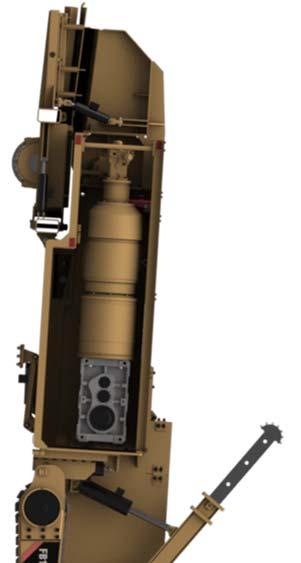
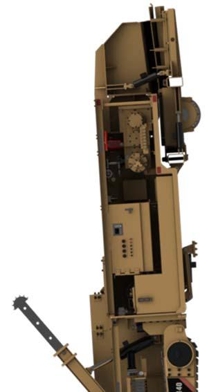
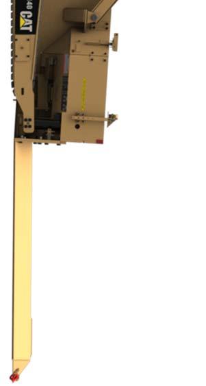
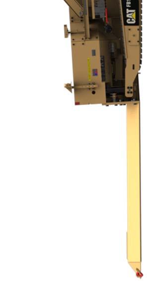
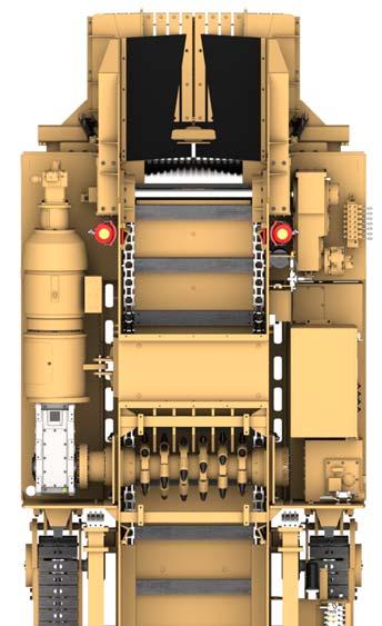
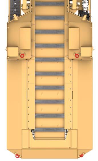
Fig. 25: Major electrical component locator
1
9
7
6 4
2
11
6 7
8
5
3
7
10
1. Breaker shaft motor 2. Breaker shaft underspeed sensor 3. Starter enclosure 4. High temp switch 5. Water solenoid 6. Photo cell (2) 7. Panic strips 8. Conveyor motor 9. Radio control box 10. Photo eye control box 11. Low oil switch
The breaker motor is a 200 HP, 575 VAC, 3 phase, 60 Hz, 1750 rpm, totally enclosed, fan cooled non-explosion proof electric motor.
The breaker shaft underspeed sensor is mounted on the breaker shaft assembly and monitors the speed of the breaker shaft. If the breaker shaft speed falls below a preset value, the electric motors will shut off.
The starter enclosure is located on the left side of the machine and houses the machines electrical controls.
The low oil switch is mounted inside the oil tank. The electric motor will shut off if the oil level in the tank falls below a preset value.
The high temperature switch is mounted on the wall behind the oil tank on the left side of the machine and will shut down the machine if the hydraulic oil temperature exceeds 165° F. The temperature probe is located in the oil tank.
The water solenoid enclosure is located on the wall behind the conveyor drive reducer. When the conveyor motor forward pressure is greater than 1,000 psi, the pressure transducer signals the PLC to open the electric water valve, activating the dust sprays and the oil cooler (water over oil heat exchanger).
The photo eye sensors are used to remotely start the conveyor/pump motor and are mounted on top of the machine on both sides of the hopper. The conveyor/pump motor will start when a light shines on the sensor for approximately four seconds.
There is one panic strip located near the valve bank on the left side of the machine and one panic strip located near the main grease manifold on the right side of machine. The third panic strip is located above the auxiliary valve bank on the left hand side of machine. Activating either panic strip will open both master control relays, “MCR” and “MCRA”, thereby shutting down the machine.
The remote pushbutton stations (2) are attached with 50 ft. cables and are mounted in the entry to allow the shuttle operator to remotely start and stop the conveyor.