BI620958
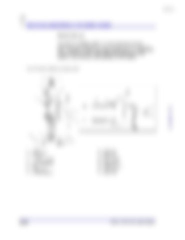
Mechanical assemblies on the feeder breaker Grease take-up The machine is equipped with a conveyor chain grease take-up assembly (Fig. 23) that provides ease of adjustment for the conveyor chain. The take-up assembly provides constant tension on the tail shaft around which the conveyor chain rides at the receiving end of the machine. (See Conveyor chain adjustment in this chapter)
Fig. 23: Grease take-up components
1. 2. 3. 4. 5. 6. 7. 8. 9.
5.24
manifold stop valve (2) union (4) r. h. hose assembly l .h. hose assembly take-up cylinder (2) tee grease fitting auto relief indicator
10. 11. 12. 13. 14. 15. 16. 17. 18.
adapter (2) check valve cap screw (2) retainer pin (2) washer (flat) (2) cotter pin (2) washer (lock) (2) nut (hex) (2) shim set (2)
Model 7SFBH-56 Feeder Breaker


