3 minute read
Tail shaft ...............................................................................5


Instructions on the replacement of wear parts
Tail shaft
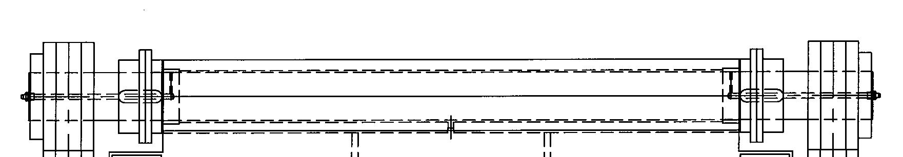
The tail shaft (Fig. 45) allows for even adjustments friction free transition to the conveyor chain assembly. As soon as any component of the tail shaft is worn the component or complete tail shaft assembly must be replaced. Due to the high abrasion forces the tail shaft is subject to a very high level of wear.
The tail shaft assembly consists of the following main components:
shaft roller (2) slide plate key (2) set screw (2) roller bearing (2) piston rod adapter (2) grease fitting (2)
Fig. 45: Tail shaft main components
Roller (2) Tail shaft Grease fitting (2)

Key (2) Set screw (2) Slide plate Roller bearing (2) Piston rod adapter (2)
Model 7SFBH-56 Feeder Breaker
Instructions on the replacement of wear parts
How to remove the tail shaft
To remove the tail shaft assembly from the receiving boom proceed as follows (Fig. 46):
Release tension on the conveyor chain. (See Conveyor chain adjustment in this chapter). Lift up the tail shaft cover plate. Disconnect, tag, and cap the central lubrication hoses to the tail shaft. Remove the three (3) bolts and lock washers from each of the tail shaft retainers and lift out the retainers. Remove the tail shaft shims. Separate conveyor chain and fold back to clear tail shaft. (See
Conveyor chain replacement in this chapter) Lift out the tail shaft and repair as required.
How to install the tail shaft
To install the tail shaft assembly into the receiving boom proceed as follows (Fig. 46):
Insert tail shaft into receiving boom. Fold the conveyor chain back over tail shaft. Connect conveyor chain (see Conveyor chain replacement in this chapter). Adjust tension on the conveyor chain (see Conveyor chain adjustment in this chapter). Install the tail shaft retainers with the three (3) bolts and lock washers in each side. Connect central lubrication hoses and lubricate tail shaft and slide plate bearings with Spec. 100-3 grease. With machine running, visually inspect tail shaft to ensure that the shaft is turning and conveyor chain is not sliding across tail shaft.
A6474X234 VUVE/01
5.59
Instructions on the replacement of wear parts
Fig. 46: Tail shaft removal and installation
Tail shaft retainers (Located under cover plate) Tail shaft cover plate

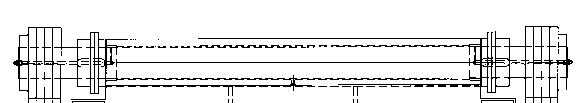
Tail shaft (Located under cover plate)
Model 7SFBH-56 Feeder Breaker
Instructions on the replacement of wear parts
How to disassemble the tail shaft
To disassemble the tail shaft assembly proceed as follows (Fig. 47):
Remove the tail shaft assembly from the receiving boom. (see How to remove the tail shaft in this chapter) Slide both roller bearings and piston rod adapters from the tail shaft. Remove the set screws from both tail shaft rollers and slid rollers from the shaft. Remove both keys from shaft. Remove the tail shaft from the slide plate. Visually inspect all components for damage or wear and replace as necessary.
How to assemble the tail shaft
To assemble the tail shaft assembly proceed as follows (Fig. 47):
Thoroughly clean any parts that will be re-installed. Grease tail shaft with Spec. 100-3 grease. Slide tail shaft into the slide plate. Insert keys into keyways on tail shaft. Slide both rollers onto tail shaft, one on each end. Install set screws into both rollers, ensuring that rollers and tail shaft slide plate are centered on tail shaft. Tighten set screws. Install both roller bearings and adapter plates on tail shaft, one on each end. Install grease fittings, if required. Install assembled tail shaft into machine. (See How to install the tail shaft in this chapter)
A6474X234 VUVE/01
5.61
Instructions on the replacement of wear parts
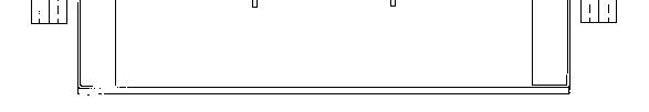
Fig. 47: Tail shaft disassembly and assembly
Roller (2) Tail shaft Grease fitting (2)
Key (2) Set screw (2) Slide plate Roller bearing (2) Piston rod adapter (2)
Model 7SFBH-56 Feeder Breaker