1 minute read
Head shaft sprockets............................................................5


Instructions on the replacement of wear parts
Head shaft sprockets
The head shaft sprocket transmits the torque of the hydraulic to the conveyor chain assembly. It is part of the head shaft assembly. As soon as the sprockets are worn they must be replaced. Due to the high abrasion forces the chain sprockets are subject to a very high level of wear.
How to remove the head shaft sprockets
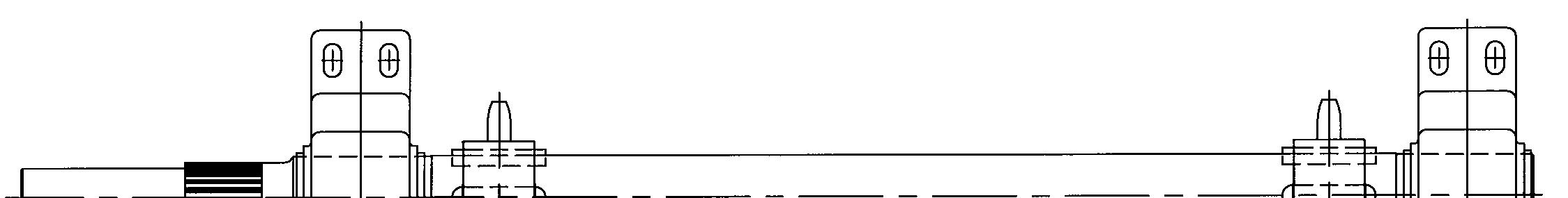
To remove the sprockets from the head shaft assembly proceed as follows (Fig. 44):
Remove the drive shaft assembly from the discharge boom (see
Drive shaft removal in this chapter). Remove the two (2) bearings from the head shaft. Remove the two set screws from each sprocket. Slide both sprockets from the drive shaft. Remove old keys. Inspect all components of the drive shaft for wear and damage. See parts manual for replacement parts list.
How to install the head shaft sprockets
To install the sprockets on the head shaft assembly proceed as follows (Fig. 44):
Thoroughly clean and lubricate the drive shaft with Spec. 100-3 grease. Insert one of the keys into the shaft keyway and slide first sprocket onto shaft and tighten the two set screws to secure the sprocket. Slide the long spacer onto the shaft. Insert the other key into the shaft keyway and slide second sprocket onto shaft and tighten the two set screws to secure the sprocket. Slide both bearings onto shaft. Install the drive shaft assembly in the discharge boom. (See drive shaft installation in this chapter)
Model 7SFBH-56 Feeder Breaker
Instructions on the replacement of wear parts
Fig. 44: Head shaft sprocket removal and installation
Bearing (2) Key (1) per sprocket Sprocket (2)
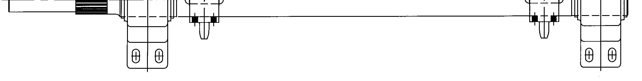
Set screw (2 ) per sprocket
A6474X234 VUVE/01