9 minute read
Breaker assembly.................................................................5


Instructions on the replacement of wear parts
Breaker assembly
The breaker assembly (Fig. 49) is assembled as a complete unit and should be removed as a unit for repairs except for the replacement of the shear hub assembly, bits and magnetic cutoff assembly. As soon as any component of the breaker assembly is worn or damaged, the component or complete assembly must be replaced.
The breaker assembly consists of the following main components:
breaker shear hub assembly bearing housing (2) bearing (2) bits (46) bearing retainer (2) magnetic cutoff assembly seal washer (3) breaker side plate (2) retaining cap dust cover shims
Fig. 49: Breaker assembly components
1. breaker shaft 7. bearing retainer (2) 12. 19 gauge wire 17. shim .06”(2) 2. shear hub assembly 8. magnetic cutoff assembly 13. retaining cap 18. cap screw 1 ¾”(160 3. bearing housing (2) 9. sealwasher (3) 14. dust cover (2) 19. cap screw 1”(8) 4. bearing (2) 10. cap screw 2 ½”(3) 15. shim .25”(2) 20. cap screw 2 ¼”(6) 5. bit (46) 11. breaker side plate (2) 16. shim .12”(2) 21. lockwasher 1”(6) 6. retaining ring (46)
A6474X234 VUVE/01
5.67
Instructions on the replacement of wear parts
How to remove the breaker assembly
To remove the breaker assembly from the machine proceed as follows (Fig. 50):
Remove covers and guards as required to gain access to the breaker assembly. Disconnect electrical wiring to the magnetic cutoff assembly. Disconnect, tag and cap the two (2) bearing central lubrication hoses. Attach an appropriate lifting device to support the breaker assembly.
WARNING! You could be seriously injured or even killed by falling loads. Observe the safe working load limits of lifting or blocking devices and keep a safe distance from suspended loads.
Remove the breaker drive chain. (See Breaker drive chain replacement in this chapter) Ensure that the breaker assembly is adequately supported and remove the bolts and lock washers that secure the breaker side plates, twelve (12) per side. Slowly lift the complete assembly out of the frame.
How to install the breaker assembly
To install the breaker assembly into the machine proceed as follows (Fig. 50):
Attach an appropriate lifting device to the breaker assembly and slowly lift the assembly into the frame.
WARNING! You could be seriously injured or even killed by falling loads. Observe the safe working load limits of lifting or blocking devices and keep a safe distance from suspended loads.
Align mounting holes in the side plates with the desired holes in the frame of machine. Secure breaker assembly with the breaker side plate mounting bolts and lock washers, twelve (12) per side. Install the breaker drive chain. (See Breaker drive chain adjustment in this chapter) Connect electrical wiring to the magnetic cutoff assembly. Connect the two (2) bearing central lubrication hoses. Install all covers and guards that were removed.
Model 7SFBH-56 Feeder Breaker
Instructions on the replacement of wear parts
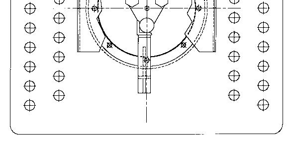
Fig. 50: Breaker assembly removal and installation
Mounting bolt location (Quantity of 6 per side)
Breaker assembly Breaker side plate (Typical on both sides of machine) Mounting bolt location (Quantity of 6 per side)

A6474X234 VUVE/01
5.69
Instructions on the replacement of wear parts
How to disassemble the breaker assembly
To disassemble the breaker assembly proceed as follows (Fig. 51):
Remove the breaker assembly from the machine. (See How to remove the breaker assembly in this chapter)
To disassemble the drive side of the breaker assembly proceed as follows (Fig. 51):
Remove the retaining cap (item 13) from the shaft by removing the locking wire (item 7), three bolts (item 10) and seal washers (item 9). Remove the shear hub assembly (item 2) from the breaker shaft. Remove grease fitting from bearing housing (item 3). Remove the breaker side plate (item 11) from the shaft by removing the three bolts (item 20) and lock washers (item 21). Remove bearing retainer (item 7) from the shaft by removing the eight bolts (item 18). Remove bearing housing (item 3) by removing the four bolts (item 19). Remove the bearing assembly (item 4). The bearing has a loose cone and cup fit, which should allow the bearing to slide off the shaft without the use of a press.
IMPORTANT! If the bearing has been allowed to fail completely, it may be necessary to cut the bearing from the shaft, using a torch. If a torch is required, care should be taken to prevent gauging or overheating of the shaft in the area of the bearing fit.
Remove dust cover (item 14). Visually inspect all components for damage or wear and replace as necessary.
Model 7SFBH-56 Feeder Breaker
Instructions on the replacement of wear parts
To assemble the drive side of the breaker assembly proceed as follows (Fig. 51):
Install dust cover (item 14) onto shaft. Install bearing assembly (item 4). The bearing should slide onto shaft with a minimal amount of force. Do not press against the outer case of the bearing. If a slight force is required, press only on the wear ring that the lip of the bearing seal bears on. Install bearing housing (item 3) and secure with the four bolts (item 19). Install bearing retainer (item 7) and secure with the eight bolts (item 18). A .06”gap must be maintained between bearing retainer (item 7) and bearing housing (item 3). Shim as required with shims (items 15, 16, and 17). Install the breaker side plate (item 11) and secure with the three bolts (item 20) and lock washers (item 21). Install grease fitting in bearing housing (item 3). Install the shear hub assembly (item 2) on the shaft. Install the retaining cap (item 13) and secure with the three bolts (item 10) and seal washers (item 9). Apply a coat of Permatex gasket sealer to each seal washer prior to installation. Torque bolts to 140 - 150 ft-lbs and secure with locking wire (item 7).
IMPORTANT! Apply a coat of Permatex gasket sealer to each seal washer prior to installation. Torque bearing end cap bolts to 140 - 150 ft-lbs and secure with locking wire (item 7).
A6474X234 VUVE/01
5.71
Instructions on the replacement of wear parts
To disassemble the magnetic cutoff side of the breaker assembly proceed as follows (Fig. 51):
Remove the magnetic sensor (item 8) from it’s mounting bracket Remove the magnetic sensor mount and retaining cap (item 13) from the shaft by removing the locking wire (item 7), three bolts (item 10) and seal washers (item 9). Remove grease fitting from bearing housing (item 3). Remove the breaker side plate (item 11) from the shaft by removing the three bolts (item 20) and lock washers (item 21). Remove bearing retainer (item 7) from the shaft by removing the eight bolts (item 18). Remove bearing housing (item 3) by removing the four bolts (item 19). Remove the bearing assembly (item 4). The bearing has a loose cone and cup fit, which should allow the bearing to slide off the shaft without the use of a press.
IMPORTANT! If the bearing has been allowed to fail completely, it may be necessary to cut the bearing from the shaft, using a torch. If a torch is required, care should be taken to prevent gauging or overheating of the shaft in the area of the bearing fit.
Remove dust cover (item 14). Visually inspect all components for damage or wear and replace as necessary.
Model 7SFBH-56 Feeder Breaker
Instructions on the replacement of wear parts
To assemble the magnetic cutoff side of the breaker assembly proceed as follows (Fig. 51):
Install dust cover (item 14) onto shaft. Install bearing assembly (item 4). The bearing should slide onto shaft with a minimal amount of force. Do not press against the outer case of the bearing. If a slight force is required, press only on the wear ring that the lip of the bearing seal bears on. Install bearing housing (item 3) and secure with the four bolts (item 19). Install bearing retainer (item 7) and secure with the eight bolts (item 18). A .06”gap must be maintained between bearing retainer (item 7) and bearing housing (item 3). Shim as required with shims (items 15, 16, and 17). Install the breaker side plate (item 11) and secure with the three bolts (item 20) and lock washers (item 21). Install grease fitting in bearing housing (item 3). Install the magnetic sensor mount and retaining cap (item 13) and secure with the three bolts (item 10) and seal washers (item 9).
Apply a coat of Permatex gasket sealer to each seal washer prior to installation. Torque bolts to 140 - 150 ft-lbs and secure with locking wire (item 7).
IMPORTANT! Apply a coat of Permatex gasket sealer to each seal washer prior to installation. Torque bearing end cap bolts to 140 - 150 ft-lbs and secure with locking wire (item 7).
Install the magnetic sensor (item 8) into it’s mounting bracket
A6474X234 VUVE/01
5.73
Instructions on the replacement of wear parts
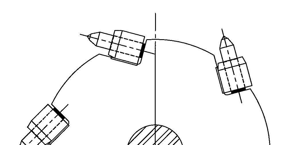
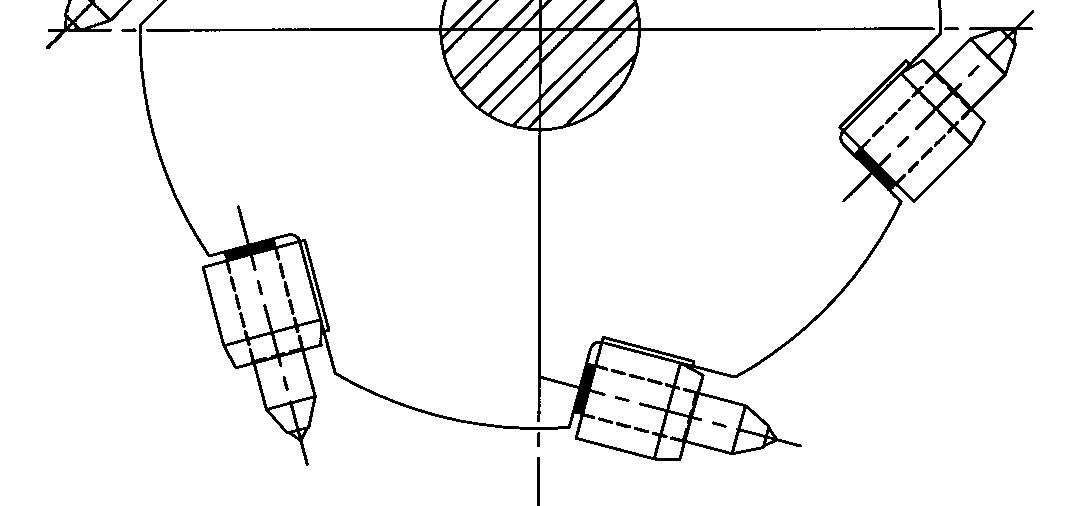
Fig. 51: Breaker assembly and disassembly
1. breaker shaft 7. bearing retainer (2) 12. 19 gauge wire 17. shim .06”(2) 2. shear hub assembly 8. magnetic cutoff assembly 13. retaining cap 18. cap screw 1 ¾”(160 3. bearing housing (2) 9. sealwasher (3) 14. dust cover (2) 19. cap screw 1”(8) 4. bearing (2) 10. cap screw 2 ½”(3) 15. shim .25”(2) 20. cap screw 2 ¼”(6) 5. bit (46) 11. breaker side plate (2) 16. shim .12”(2) 21. lockwasher 1”(6) 6. retaining ring (46)
Model 7SFBH-56 Feeder Breaker
Instructions on the replacement of wear parts
How to remove the breaker bit
To remove the breaker bit from the breaker shaft bit holder proceed as follows (Fig. 52):
Remove the external retaining ring from the shank end of the bit with a pair of external retaining ring pliers. Remove the bit from its holder. If the bit will not pull easily from its holder, it may be necessary to insert a bar behind the shank end of the bit and pry it out.
IMPORTANT! If the bit will not pull easily from its holder, it may be necessary to insert a bar behind the shank end of the bit and pry it out.
How to install the breaker bit
To install the breaker bit in the breaker shaft bit holder proceed as follows (Fig. 52):
Clean any dirt or debris from inside or around the holder and insert the shank end of the bit into the bit holder. Install the external retaining ring on the shank end of the bit with a pair of external retaining ring pliers. Ensure that the retaining ring is completely seated inside grooved area of the bit.
Fig. 52: Breaker bit removal and installation
Side view of breaker Breaker bit
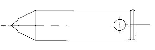
Retaining ring
A6474X234 VUVE/01