1 minute read
Starter enclosure 5


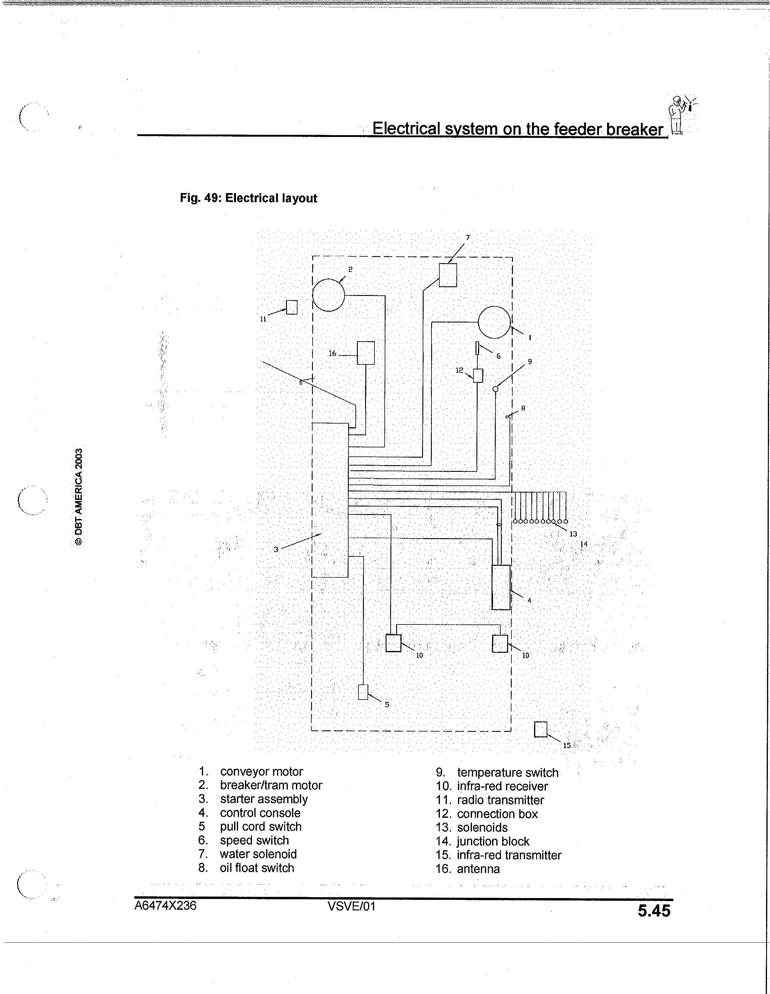
Fig. 49: Electrical layout
Electrical system on. the feeder breaker ,
0 DBT AMERICA 2003
1. conveyor motor 2. breaker/tram motor 3. starter assembly 4. control console 5 pull cord switch 6. speed switch 7. water solenoid 8. oil float switch
A6474X236 VSVE/01 9. temperature switch 10. infra-red receiver 11. radio transmitter 12. connection box 13. solenoids 14. junction block 15. infra-red transmitter 16. antenna
5.45
tElectrical system on the feeder breaker
Starter enclosure
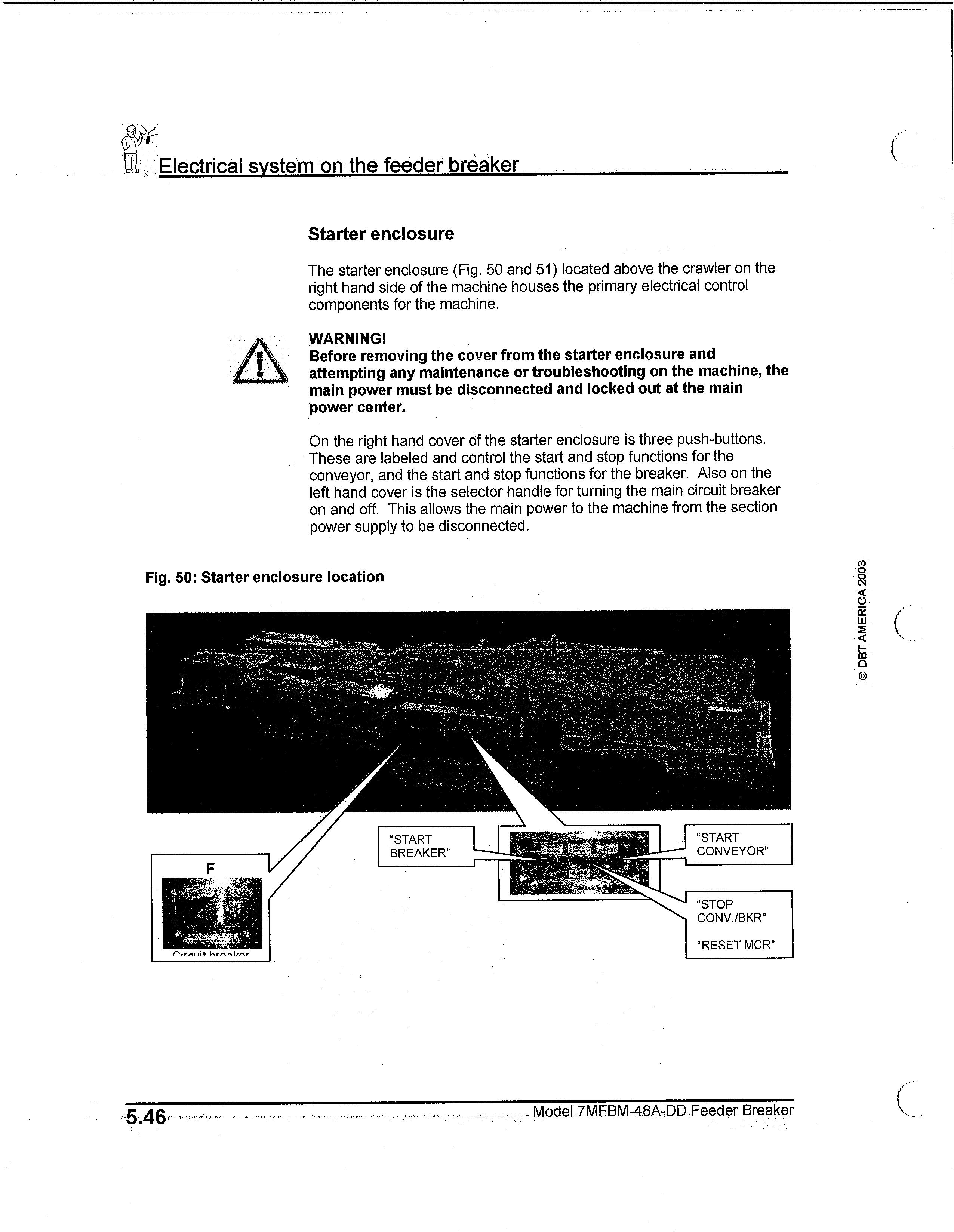
The starter enclosure (Fig. 50 and 51) located above the crawler on the right hand side of the machine houses the primary electrical control components for the machine.
WARNING! Before removing the cover from the starter enclosure and attempting any maintenance or troubleshooting on the machine, the main power must be disconnected and locked out at the main power center.
On the right hand cover of the starter enclosure is three push-buttons. These are labeled and control the start and stop functions for the conveyor, and the start and stop functions for the breaker. Also on the left hand cover is the selector handle for turning the main circuit breaker on and off. This allows the main power to the machine from the section power supply to be disconnected.
Fig. 50: Starter enclosure location
ERICA 200 3 C DBT AM
5.46,
Model .7MFBM-48A-DaFeeder Breaker