1 minute read
Tail piece valve bank controls (Optional) 5


--How to operate the feeder breaker
Tail piece valve bank controls (Optional)
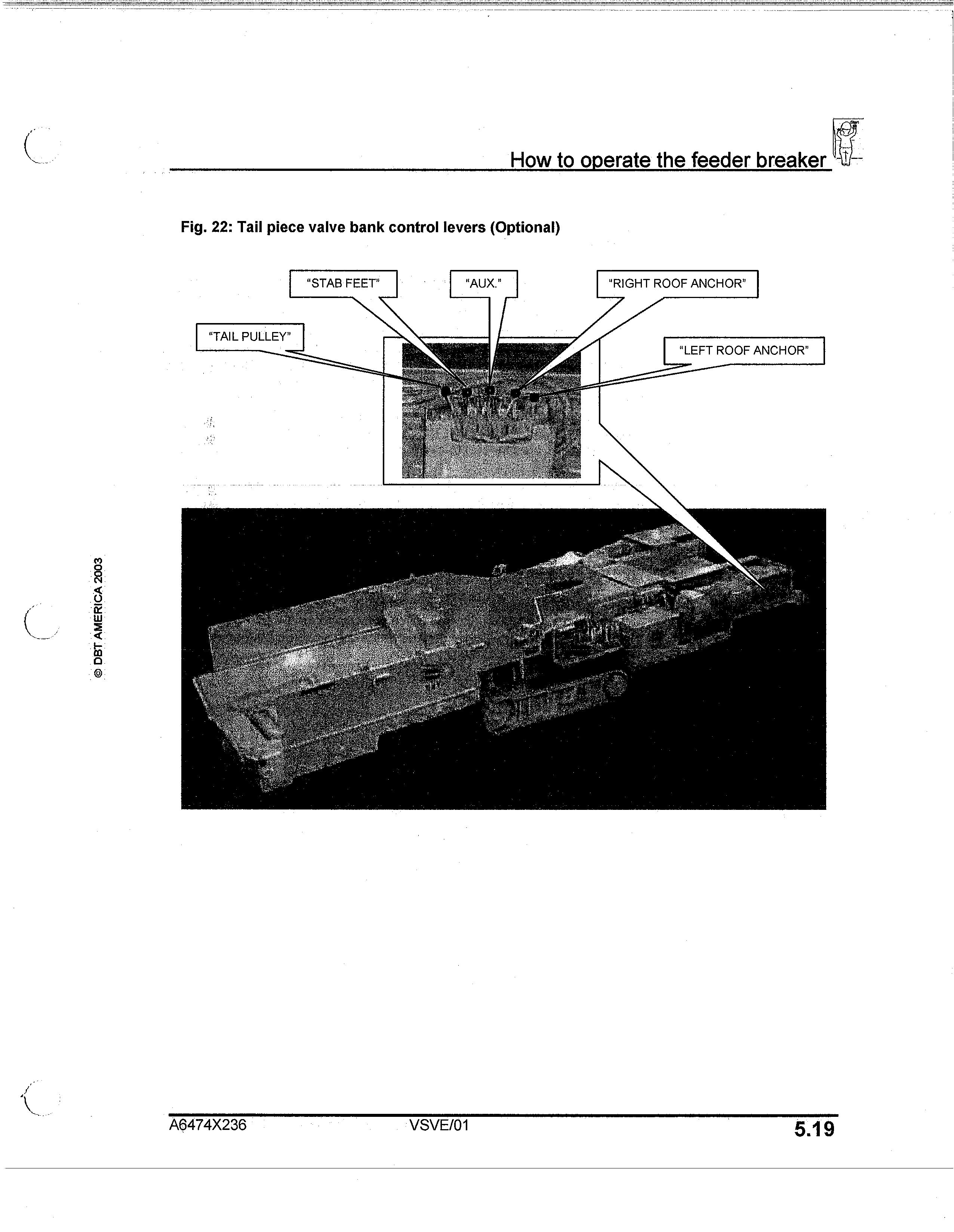
The optional tail piece control valve bank (Fig. 22) is located on the left hand side near the feeder assembly consists of the following hydraulic controls:
IMPORTANT! The PTO control valve section located at the operator's station must be actuated before the PTO valve bank can be operational.
NOTICE! Once either of the hydraulic control valve handles is released by the operator, the lever will automatically return to the centered (neutral) position.
The first lever from the operator's left controls the movement of the two (2) cylinders mounted on each side of the tail pulley assembly. To align the tail pulley, slowly push or pull the control lever until the correct alignment is achieved and then release handle.
"STAB FEET"
The second lever from the operator's left controls the movement of the two (2) cylinders mounted on each side of the impact bed assembly. To raise the impact bed, slowly push the control lever away from the operator and to lower the impact bed, slowly pull the control lever towards the operator.
"AUX." The third lever from the operator's left controls the auxiliary section of the valve bank.
DBT AMERICA 2003
5.18
Model 7MFBM-48A-DD Feeder Breaker
How to operate the feeder breaker
Fig. 22: Tail piece valve bank control levers (Optional)
"TAIL PULLEY"
© DBT AMERICA 20 0
A6474X236 VSVE/01