III. Presentation
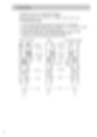
D. Main structure of hydraulic breaker Breaker consists of five main sections such as Cylinder, Piston, Control valve, Front head and Back head. 1. 2. 3. 4. 5. 6.
Four through bolts are holding cylinder, back head and front head together. Cylinder contains piston, control valve and accumulator where Nitrogen gas is charged. Piston strikes the working tool by oil & gas pressures. Control valve located inside cylinder determines direction of piston movement. Tool pins are located inside front head, limiting tool stroke distance. Back head has a chamber where Nitrogen gas is charged.
CB20, CB40, CB60
CB80
Through bolt Back head
Control valve Cylinder Piston
CB140, CB210, CB380 Through bolt Back head
Control valve Cylinder Piston Accumulator
Front head
Tool pin
Tool
8
Front head
Tool pin
Tool


