2 minute read
COOLING SYSTEM


COOLING SYSTEM Service specifications
Coolant reservoir level check..........................................................Every 10 hours or every day Check tightening of clamps and hoses.........................................Every 250 hours Drain and rinse..............................................Every 2000 hours or every two years System capacity..........................................................................................31 liters Thermostat range...............................................................................82°C to 94°C Reservoir cap pressure..............................................................................1.03 bar
WARNING: Boiling coolant can spray out if the coolant reservoir cap is removed while the system is still hot. Before removing the cap, let the system cool down, then turn the cap to the first notch, and wait until the pressure is released. Then remove the cap.
WARNING: Check and service the cooling system according to the instructions given in this manual.
!
Coolant solution
Only put ethylene-glycol and water coolant solution in the cooling system. Use good quality ethylene-glycol that has a high boiling point, with no additives to prevent leakage. Do not use non-approved anti-rust additives. Anti-rust additives and ethylene-glycol can mix and work against each other, thereby reducing anticorrosion protection, forming deposits in the cooling system and causing damage to the cooling system and radiator. Consult your CASE Dealer for a suitable coolant solution.
The level of coolant solution should be checked when the engine is cold. WARNING: Do not remove the reservoir cap while the engine is hot. The cooling system will still be under pressure and you could be scalded.
STEP 2
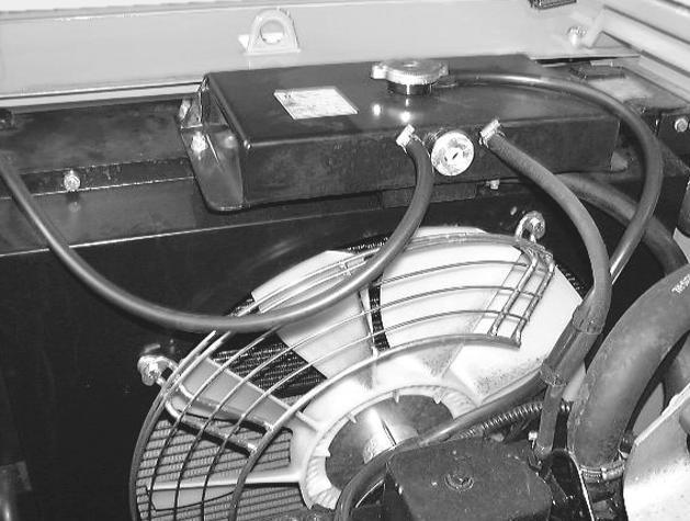
CD00B006 Check the level on flat, level ground, before using the machine (while the engine is still cold). The level in the coolant reservoir should be in the middle of the sight glass. If not, see “Filling” .
Draining
Tools required
-One 17 mm wrench for hexagonal head screws -One flat-headed screwdriver
STEP 1
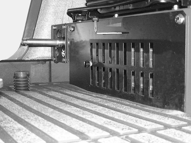
CD99N001 Move the heating control to the left (open).
STEP 3
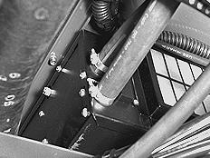
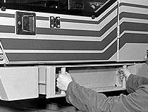
PG03004 Remove the screws and the lower tray under the operator’s compartment.
CD00B006 Remove the coolant reservoir cap.
STEP 4 Filling
Tools required
-One 17 mm wrench for hexagonal head screws -One flat-headed screwdriver
STEP 1
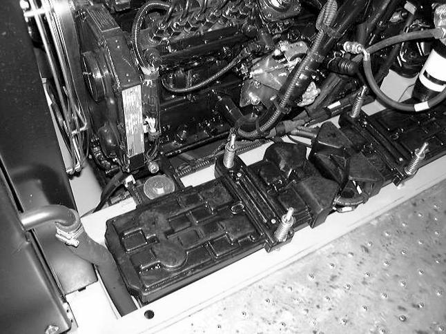
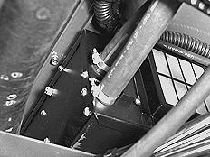
PE07509 Disconnect the hose from the heater unit and let the liquid flow out. NOTE: Use a container of an adequate capacity.
STEP 5
After the system is completely drained, reconnect the hose to the heater unit and tighten the clamp.
STEP 6
Rinse out the system with fresh water. Drain again, reconnect the hose to the heater unit and tighten the clamp. Refill the system.
CD00B006 Fill with coolant solution via the coolant reservoir until it overflows. IMPORTANT: Use a suitable coolant solution.
STEP 2
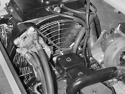
PE07509 Loosen the heater unit bleed screw, let the air escape until coolant solution starts to flow out. Then retighten the screw.