4 minute read
ATTACHING THE CASE CLAMSHELL FOR ROAD TRAVEL


IMPORTANT: (Specific to Germany), when travelling on the road, machines equipped with CASE clamshells must be driven without these tools. You must remove these tools before travelling on the road. This procedure for attaching the clamshell is given for a machine equipped with a 2.10m dipper, with bucket cylinder and bucket control and a set of 10.00-20 tyres.
P, PL and P2A Versions
STEP 1 STEP 2
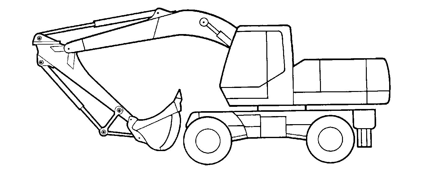
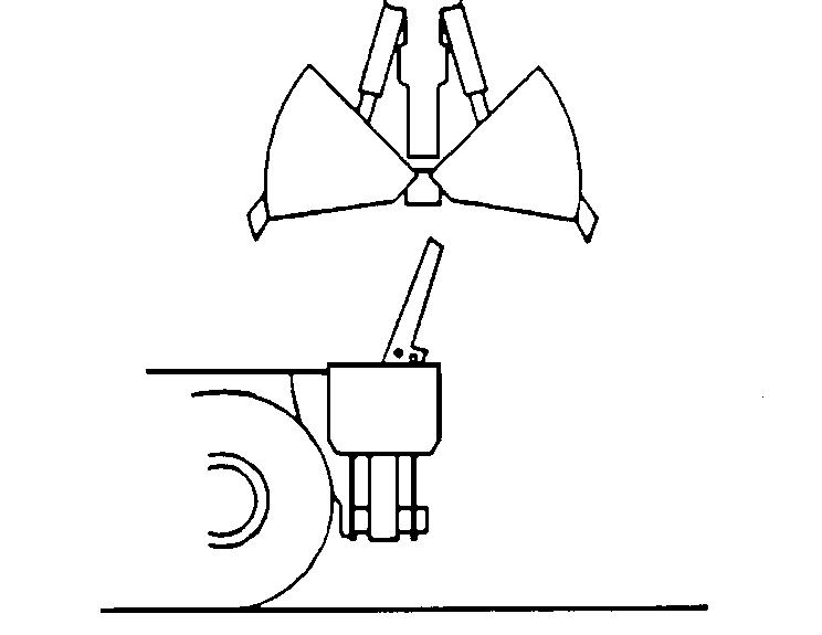
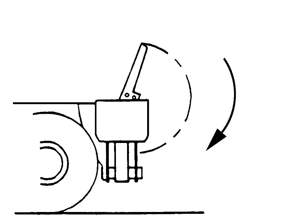
Turn the clamshell to the vertical position so that its teeth are between the undercarriage front lugs.
1
2

1
PDH1078 Install the attaching bar (1) in the bores (2) of the undercarriage front lugs. The split pin end of the bar (1) must be visible to the operator.
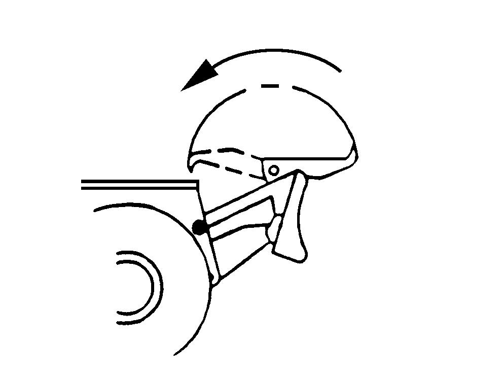
PDH1079 Using the boom and dipper, position one shell of the clamshell on the attaching bar (1) at the front of the undercarriage.
STEP 3 STEP 5
1

With articulated boom

PDH1080
Hook the teeth of both shells onto the bar (1) by operating the boom cylinders, the boom articulation cylinders, the dipper cylinders and the clamshell closing cylinders at the same time. The attachment will be within the approved road travel overall dimensions when the boom cylinders and boom articulation cylinders are completely extended.
STEP 4
Lock the boom and dipper positions using the boom and dipper locking valves. See “Boom locking valve” and “Dipper locking valve” in the “Controls/Instruments/ Accessories” Section. 3 2

1
PDH1081 Install the shell locking hook (1) by hooking it onto the side of the lower shell and fitting it into the attaching bar (2) at the operator’s compartment end. Keep the hook (1) in place by means of a safety split pin. Install the marker light (3) on the dipper.
P2A+2A Version
STEP 1
2 1
PDH1082 Turn the clamshell so that the clamshell teeth are parallel with the face of the stabilizer beam. Install the clamshell support (1) on the fittings provided for that purpose on the beam. Install the four retaining pins (2) and their split pins.

PDH1083 Raise the clamshell and open it so that it is above the support.
STEP 3
PDH1084 Using the boom and dipper, bring one shell of the clamshell in contact with the front support on the undercarriage.
With articulated boom

PDH1085
Extend the boom cylinders and swing the clamshell around the support by operating the boom articulation cylinders and the dipper cylinders simultaneously. The attachment will be within the approved road travel overall dimensions when the boom cylinders and boom articulation cylinders are completely extended and the clamshell beam is in contact with the stabilizer beam.
STEP 5
Lock the boom and dipper positions using the boom and dipper locking valves. See “Boom locking valve” and “Dipper locking valve” in the “Controls/Instruments/ Accessories” Section.
STEP 6
1
STEP 2

PDH1086 For the work position, remove the pins (1) and then tilt the support forwards. Lock the support with one of the pins.
P2AL Version
STEP 1
PDH1088 Raise the clamshell and open it so that it is above the support.
STEP 3

PDH1087 Turn the clamshell so that the clamshell teeth are parallel with the face of the blade. Install the support on the blade after pulling the retaining pins out of the blade support rods. Reposition the retaining pins and split pins in their initial position.

PDH1089 Using the boom and dipper, bring the shell beam, located towards the operator’s compartment into the housing provided for it on the support.
With articulated boom

PDH1090
Extend the boom cylinders and swing the clamshell around the support by operating the boom articulation cylinders and the dipper cylinders simultaneously. The attachment will be within the approved road travel overall dimensions when the boom cylinders and boom articulation cylinders are completely extended and the clamshell beam is in position in its housing on the support.
STEP 5
Lock the boom and dipper positions using the boom and dipper locking valves. See “Boom locking valve” and “Dipper locking valve” in the “Controls/Instruments/ Accessories” Section.
PDH1091 For the work position, tilt the support towards the undercarriage until it is stopped by the blade support rods.