7 minute read
ROAD TRAVEL


WARNING: Before travelling on the road, you must lock the attachments and install the safety systems required by regulations. The stabilizers (if fitted) must be raised completely and immobilized using the lock pins and split pins. The stabilizer pads must be in the swivel position. The dozer blade (if fitted) must be raised and immobilized using the lock pin and split pin.
WARNING: Before travelling on the road, make sure that the load on each axle, depending on the machine configuration, conforms to the road traffic regulations of the country concerned.
WARNING: All road travel must be undertaken in forward drive.
WARNING: Use of the electric travel control (if fitted) is strictly forbidden during road travel.
WARNING: (Specific to Germany), when travelling on the road, machines equipped with CASE clamshells must be driven without these tools. You must remove these tools before travelling on the road.
STEP 1

CD98J005 Raise the stabilizers (if fitted) completely.
STEP 2
CD99N045 Immobilize the stabilizers using the lock pins and split pins located in the tool box.
STEP 3 STEP 5

CD99N004 Remove the lock pins and split pins from the stabilizer pads so that they are in the swivel position, then place the lock pins and split pins in the tool box.
STEP 4

CD99M022 Engage the upperstructure swing lock pin.
STEP 6
PH00620 Raise the dozer blade (if fitted) and immobilize it, using the lock pin and split pin located in the tool box.

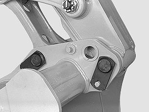
PG02804A The bucket linkage point must be in the maximum force position. See “Backhoe bucket maximum opening range and maximum force positions” in the “Controls/Instruments/Accessories” Section. If it is not, change the linkage position. See “Replacing a backhoe bucket” in the “Maintenance/Adjustments” Section.

PH08024
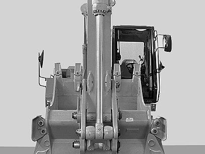
(Machine with bucket)
Extend the bucket cylinder rod completely and bring the bucket to the stop on the front of the machine.
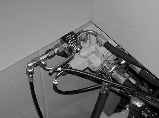
PG01930 Take the bucket/clamshell selector valve lever from the tool box and install it on the valve. Turn the valve lever downwards to the closed position, then remove the lever and put it back in the tool box.
STEP 9

CD98E041

(Machine without bucket)
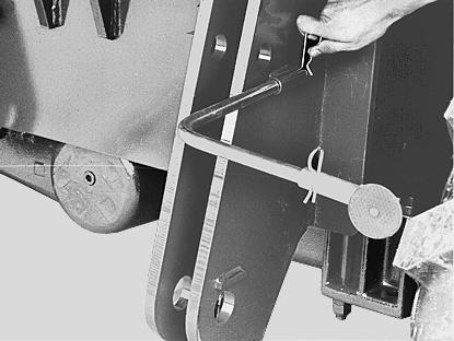
Retract the bucket cylinder rod completely and then install the locking rod, the lock pins and split pins located in the tool box (optional). Then bring the dipper to the stop on the front of the machine.
PDH0094 Extend the bucket cylinder rod. Install the locking system using the wing nuts and then retract the bucket cylinder rod against the stop on the locking system (specific to certain countries).
STEP 10 Sling length pre-adjustment (Specific to certain countries)
Versions Boom Dipper L (total length of sling to be used)

P PL P2A
Monoblock 5.20 m 2.10 m 5.90 m 2.70 m 4.00 m 3.10 m
Offset backhoe
2.10 m 2.70 m 3.10 m 2.50 m Articuladed 2.70 m 3.30 m Handling 3.22 m
P2A + 2A
P2AL
Monoblock 5.20 m

3.10 m 3.30 m
Offset backhoe
2.10 m 3.70 m 2.70 m 1.90 m 3.10 m Articuladed 2.70 m 2.80 m Handling 1.90 m
Monoblock 5.20 m 2.10 m 2.70 m 3.80 m 3.10 m 2.30 m
Offset backhoe
2.10 m 2.70 m 2.10 m 3.10 m Articuladed 2.70 m 3.70 m Handling 1.70 m 2 1
4 3
CS99D501 Install the sling (1) in the take-up ratchet (2), making sure that measurement (L) is correct (see tabel). Pass the sling around the lifting point. Put the ring (3) inside the shackle (4). The shackle must then be attached to the towing eye on the undercarriage. Hitch the sling in the ring (3) and tighten the sling.
STEP 11 (Monoblock and offset backhoe booms)
PH07633 Position the boom so that the index rod mark is aligned with the boom cylinder mark. This position guarantees an approved height for driving on the road (specific to certain countries).
CD98J008 Position the boom by operating the boom cylinder controls and the extension cylinder controls. Extend the rods completely and bring the dipper to the stop on the front of the machine.
STEP 12

PD07508 Install the reflectors according to the machine version. See “Reflectors” in the “Instruments/Controls/Accessories” Section.
PG02707 Turn the valve lever upwards (closed position) to immobilize the boom.
STEP 14
CD99N014 If the machine is fitted with the safety valves, turn the valve lever downwards (closed position) to immobilize the boom.
STEP 15 (SpecifictoGermany)

CD99G032 Turn the valve lever upwards (closed position) to immobilize the dipper (specific to certain countries).
STEP 16
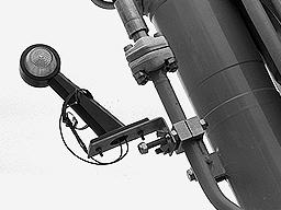
PDH0370 For a machine equipped with a 2.65 m dipper, without a bucket, the marker light must be placed on the feed pipe towards the cylinder bottom.
STEP 17

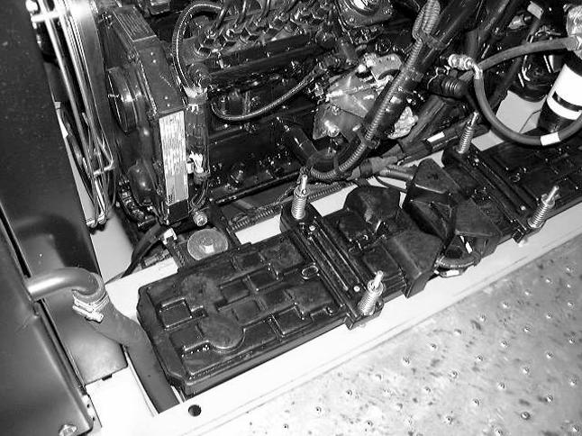
PH01111 Install the marker light on the dipper. Connect the electric cable to the electric power socket located on fuel tank and then use the lighting selector switch in the operator’s compartment to switch on the position lights (specific to certain countries).
CD95N040 Install the daytime marker plates and attach them to the dipper, using the split pins (specific to certain countries).

PG02702 Install the rotary beacon and switch on the rotary beacon from the instrument panel (specific to certain countries).
STEP 19

CD97M001 Install the warning triangle (specific to certain countries).
STEP 22

CK99K001 Place the cover over the attachment work light (specific to certain countries).
STEP 20
Install the registration plate (specific to certain countries).

CD99N010 Adjust the forward and rear view mirrors correctly.
STEP 23
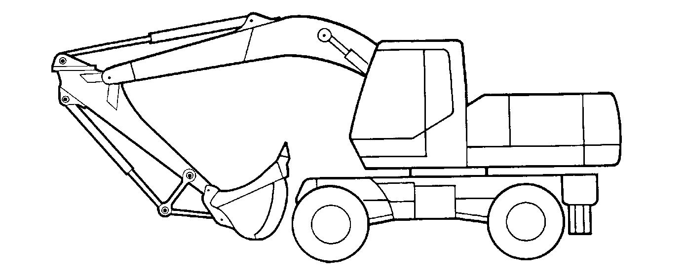
Position the attachment, depending on the configuration and the country concerned. See “Road travel overall dimensions” in the “Specifications” Section.
STEP 24 (Machine with CASE clamshell)
IMPORTANT: (Specific to Germany) It is mandatory to remove the clamshell before undertaking any road travel.
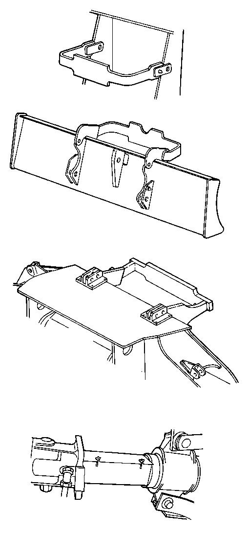

PDH0100 Position the clamshell on the undercarriage bracket, or the stabilizer or dozer blade bracket (depending on machine version). Install the shell locking system (specific to certain countries). See “Attaching the CASE clamshell for road travel” .
STEP 25

PH07328 Press down the brake pedal and select road speed “Position 2” on the control panel (right-hand indicator lamp comes on).
STEP 26
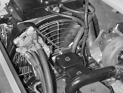
CD96H009 Switch on the pilot system cancellation control switch. The indicator lamp will light up on the instrument panel (specific to certain countries).

PH07328 Press the “MAX” push button on the control panel.
STEP 28
PH07520 Move the travel control lever completely forwards.
STEP 30

CD96H009 Release the brakes using the parking/ work brake control switch.

PH07533 Place the front axle locking/unlocking switches in the unlocked position (the indicator lamp on the instrument panel comes on).
STEP 31
Close the cab door and make sure it is securely fastened.
STEP 32
CD99M019 Control the travel speed using the travel control pedal.

WARNING: The front axle must be unlocked for all travel operations.
WARNING: When travelling, check the gauges and lamps on the instrument panel frequently. WARNING: Road travel which requires the use of dipped or main-beam headlights (travel at night, in a tunnel or in poor weather conditions, etc.) must only be undertaken with attachments in road travel position and with tools (bucket or clamshell) less than 1.15 m, in order to conform to lighting regulatory requirements.
NOTE: The machine’s steering system includes an emergency steering system. If power supply fails, this function starts up automatically, the minimal steering pressure red indicator lamp lights up on the instrument panel and the force required to turn the steering wheel is greater.
WARNING: When travelling with the hydraulic breaker (optional) make sure it is not pointing towards the cab as too close to it.