3 minute read
TOOL INSTALLATION AND REMOVAL USING THEQUICK COUPLER


Installation
WARNING: Never put your hands in the Quick Coupler while the engine is running.
IMPORTANT: When installing the Quick Coupler hydraulic system, the connecting rod must be mounted at the maximum opening range point.
STEP 1 STEP 3
1
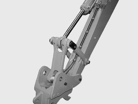
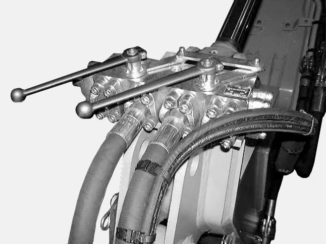
CK97A003 Install the Quick Coupler on the dipper and on the connecting rod using the pins supplied by CASE (1), and then connect the supply lines.
STEP 2
Make sure that the tool to be installed is in a safe position on flat, level ground, and equipped with genuine CASE pins.
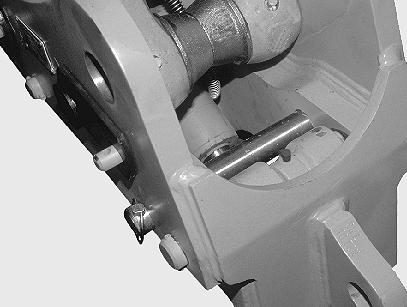
CK97A004 Make sure that the tool linkage pin is placed at the maximum opening range position. IMPORTANT: The pin must be placed at the maximum opening range position, otherwise the tool cannot be hooked onto the Quick Coupler.
STEP 4
CK97A009 Remove the split pin and retaining pin.
1 2

CK97A004 CK97A005
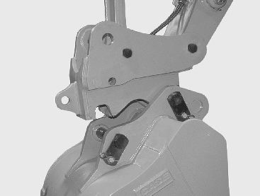
Operate the dipper control lever to bring the Quick Coupler hook (1) around the tool linkage pin (2).
STEP 6
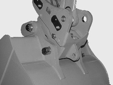
Operate the bucket control lever so that the linkage pin is completely engaged in the Quick Coupler hook.
STEP 8


CK97A002 CD00A007
Place the switch in the unlocked position. See “Quick Coupler locking/unlocking switch” in the “Controls/Instruments/ Accessories” Section. Raise the dipper and retract the bucket until the teeth are in the vertical position.
STEP 9
CK97A002 Place the switch in the locked position. See “Quick Coupler locking/unlocking control switch” in the “Controls/Instruments/Accessories” Section. IMPORTANT: Check that the Quick Coupler is properly attached to the tool linkage pins.
STEP 10
CK97A007 Install the retaining pin and the split pin. IMPORTANT: The retaining pin and split pin must be in place.

Removal
STEP 1
Place the tool on flat, level ground.
STEP 2
CK97A007 Remove the split pin and retaining pin.
STEP 3

CK97A002 Place the switch in the unlocked position. See “Quick Coupler locking/unlocking control switch” in the “Controls/Instruments/Accessories” Section.
Loader application

CK97A005 Wait for five to ten seconds to allow the hook to retract. Operate the bucket control lever so as to disengage the pin.
STEP 5
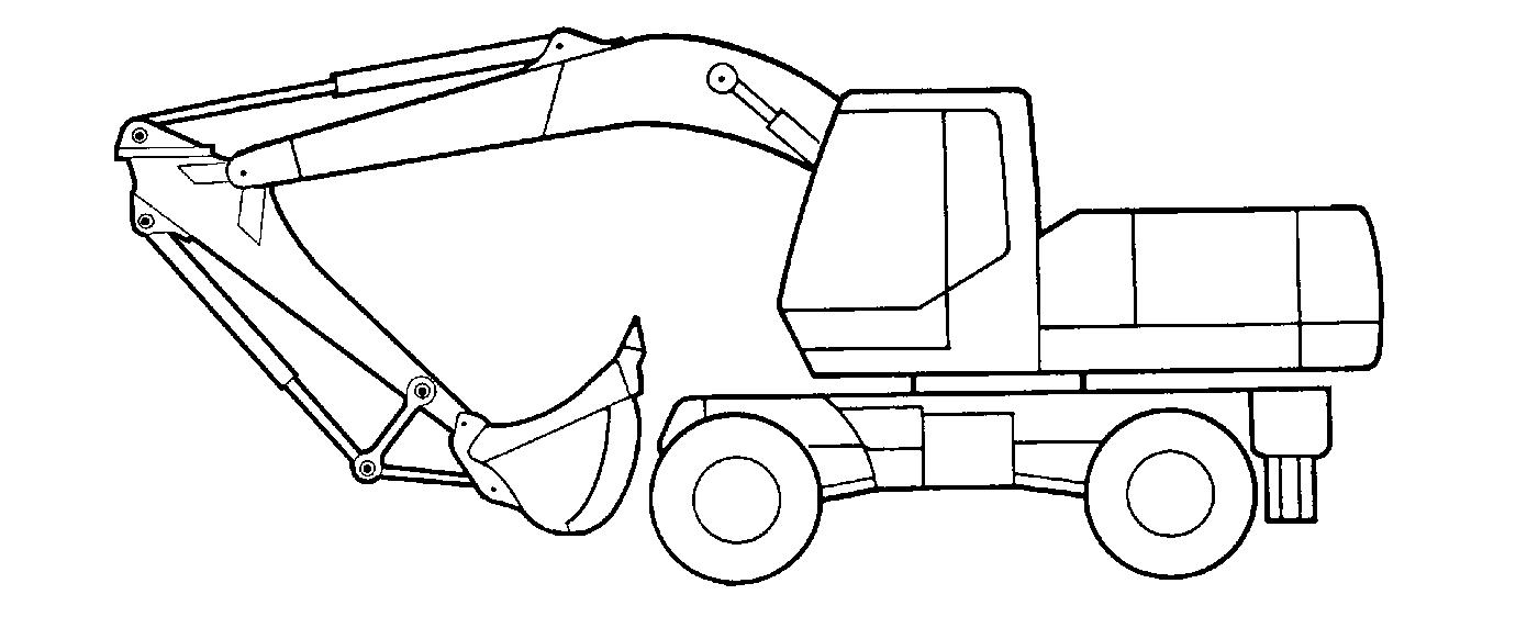
CD97H003 The Quick Coupler allows you to reverse your buckets to serve as a loader.
Clamshell installation
STEP 1

CK97A008 Operate the dipper control lever so as to disengage the bucket.

CD00A008 Mount the clamshell adaptor on the quick coupler. See “Tool installation and removal using the quick coupler”. Make sure the clamshell adaptor is correctly positioned with the linkage pin lug on the left-hand side.
STEP 2 STEP 4
CD00A009 Retract the bucket cylinder rod as far as possible. Stop the engine and remove the starter switch key.
STEP 3

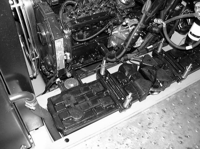
CD00A010 Take the bucket or clamshell selector valve levers out of the tool box and install them on the selector valve.

CD00A011 Turn the levers to the left, in closed position, then remove the levers and put them back in the tool box. NOTE: The quick coupler can work efficiently with hydraulic hammers, but too long periods of such work should be avoided. When you use a hydraulic hammer, you must always orientate the hammer towards the machine and never use it as a lever, since all stresses would be imposed on the quick coupler hydraulic cylinder. The quick coupler is not designed to be subjected to prolonged excessive vibration. We therefore recommend you to remove the quick coupler to reduce the risk of needless premature wear, failures or breakage.