
3 minute read
DRIVE CHAINS


Checking the Drive Chain Tension
Check the tension of the four drive chains after the first 250 hours of operation on a new machine or new chains. Then, check the tension after every 1000 hours of operation. 1.Lower the loader bucket or attachment to the ground. Turn the key switch to OFF and stop the engine. 2.Use a jack or hoist and lift the machine. Install blocks or axle stands under the machine.
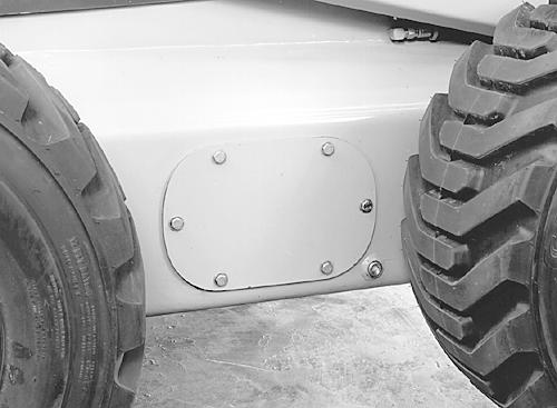
3.Clean the area around both inspection covers and remove.
1
BP96N056 1.DRIVE CHAIN INSPECTION COVER
4.Sit in the operators seat and pull the seat bar down.
5.Start the engine. 6.Push both steering control levers forward to move the machine a short distance forward.
7.Stop the engine and raise the seat bar.
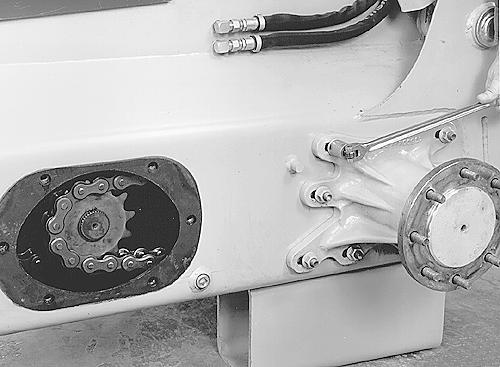
8.Check the deflection of the chain on the slack side.
BP96N061
NOTE: The deflection of the chains cannot be measured with accuracy. 9.Move the chain up and down and measure the deflection as close as possible. IMPORTANT: If the deflection is more than 40.0 mm (1.5 inch) total movement for one chain, adjust the deflection of all chains. See Adjusting the Drive Chains on page 172 of this manual.
10.Repeat this procedure on all four of the drive chains.
11.Apply sealant between gasket, cover and chassis.
12.Install the inspection covers.
Tighten the inspection cover bolts to a torque of 125 to 150 Nm (93 to 112 pound-feet). 13.Tighten the axle housing mounting bolts to a torque of 223 to 265 Nm (165 to 190 pound-feet).
Adjusting the Drive Chain Tension
1.Lower the bucket or attachment to the ground and stop the engine. 2.Use a jack or hoist and lift the machine. Install blocks or axle stands under the machine as shown. Raise loader lift arms and engage support strut. Remove the wheels.
3.Clean the area around the inspection covers and each axle housing.
1 2 1
1.AXLE HOUSING 2.INSPECTION COVERS

4.Remove the inspection covers

BP96N063 BP96N018
BP96N063
5.Loosen the axle housing mounting nuts so the axle is free to move forward or rearward.
6.Insert a pry bar against the adjusting spud and the axle housing.
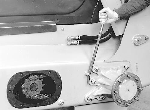
BP96N060
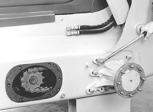
7.Pry against the axle housing until it stops moving. Tighten one or two nuts to hold the axle housing in place and check the chain deflection.
BP96N061
8.When the deflection is correct, 3.0 to 12.0 mm (0.12 to 0.50 inch) tighten the axle housing mounting nuts to a torque of 7 Nm (5 poundfeet).
BP96N059
9.Repeat the above steps for the remaining drive chains. 10.Following adjustment of all drive chains, start the engine and run at low idle.
11.Move the control levers all the way forward for five seconds. Stop the engine. 12.Check the deflection of all four drive chains. The drive chains are correctly adjusted if the deflection is 3.0 to 12.0 mm (0.12 to 0.50 inch). 13.If required, tighten or loosen the drive chains to get the correct deflection.
14.Tighten the axle housing mounting bolts to a torque of 223 to 265 Nm (165 to 190 pound−feet). 15.Apply sealant between gasket, cover and chassis and install the inspection cover.
BP96N063
16.Tighten the inspection cover mounting bolts to a torque of 125 to 150 Nm (93 to 112 pound−feet).
BP96N05
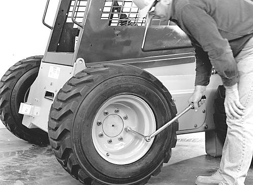
17.Install the four wheels. If the machine is equipped with stamped center wheels, the lug nuts will be tapered type lug nuts.Tighten each lug nut to a torque of 135 to 163
Nm (100 to 120 pound-feet). If the machine is equipped with solid center wheels, the lug nuts will be flange type lug nuts.Tighten each lug nut to a torque of 224 to 265
Nm (165 to 195 pound-feet). 18.Remove the blocks or stands and lower the machine to the floor.


