11 minute read
ELECTRICAL SYSTEM


Description
Figure PM-48
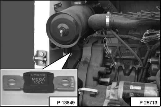
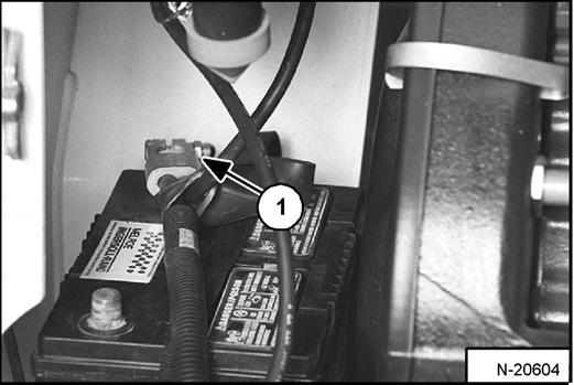
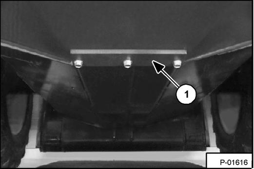
The loader has a 12 volt, negative ground alternator charging system. The electrical system is protected by fuses located in the cab on the steering control panel, and a 100 amp. master fuse (Inset) [Figure PM-48] in the engine compartment on the left side of the engine. The fuses will protect the electrical system when there is an electrical overload. The reason for the overload must be found before starting the engine again.
Cleaning Battery Terminals
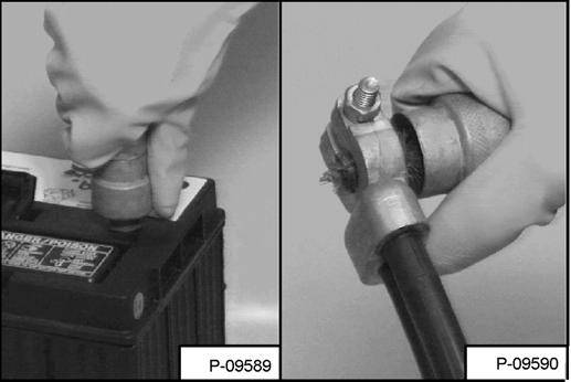
The battery cables must be clean and tight. Check the electrolyte level in the battery. Add distilled water as needed. Remove acid or corrosion from the battery and cables with a sodium bicarbonate and water solution.
Put Battery Saver P/N 6664458 or grease on the battery terminals and cable ends to prevent corrosion.
Warning
Batteries contain acid which burns eyes and skin on contact. Wear goggles, protective clothing and rubber gloves to keep acid off body.
In case of acid contact, wash immediately with water. In case of eye contact get prompt medical attention and wash eye with clean, cool water for at least 15 minutes.
If electrolyte is taken internally drink large quantities of water or milk! DO NOT induce vomiting. Get prompt medical attention.
W-2065-1296
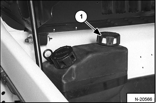
Fuse Location
Figure PM-49
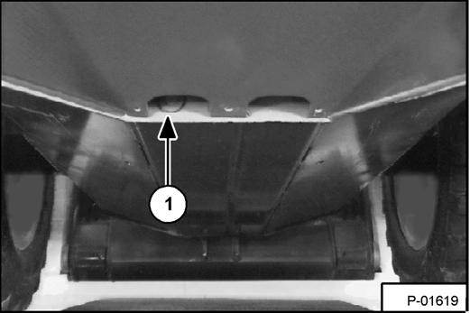
The electrical system is protected from overload by fuses and relays under the fuse panel cover (Item 1) [Figure PM-49]. A decal is inside the cover to show location and amp. ratings.
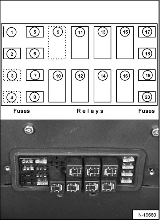
Remove the cover to check or replace the fuses.
The location and sizes are shown below and [Figure PM50]
ELECTRICAL SYSTEM (CONT’D)
Fuse Location (Cont’d)
R - Relay
Using A Booster Battery (Jump Starting)
If it is necessary to use a booster battery to start the engine, BE CAREFUL! There must be one person in the operator's seat and one person to connect and disconnect the battery cables.
The key switch must be OFF (Standard Panel) OR the STOP Button must be pressed (Deluxe Panel). The booster battery must be 12 volt.
Warning
Batteries contain acid which burns eyes and skin on contact. Wear goggles, protective clothing and rubber gloves to keep acid off body.
In case of acid contact, wash immediately with water. In case of eye contact get prompt medical attention and wash eye with clean, cool water for at least 15 minutes.
If electrolyte is taken internally drink large quantities of water or milk! DO NOT induce vomiting. Get prompt medical attention.
W-2065-1296
Warning
Keep arcs, sparks flames and lighted tobacco away from batteries. When jumping from booster battery make final connection (negative) at machine frame. Do not jump start or charge a frozen or damaged battery. Warm battery to 60°F (16°C) before connecting to a charger. Unplug charger before connecting or disconnecting cables to battery. Never lean over battery while boosting, testing or charging. Battery gas can explode and cause serious injury.
W-2066-0705
Connect the end of the first cable (Item 1) [Figure PM51] to the positive (+) terminal of the booster battery. Connect the other end of the same cable (Inset-Item 2) [Figure PM-51] to the positive terminal on the loader starter.
Connect the end of the second cable (Item 3) [Figure PM-51] to the negative (-) terminal of the booster battery. Connect the other end of the same cable (Inset-Item 4) [Figure PM-51] to the engine.
Keep cables away from moving parts. Start the engine. (See STARTING THE ENGINE on Page OI-21.)
After the engine has started, remove the ground (-) cable (Item 4) [Figure PM-51] first.
Remove the cable from the positive terminal (Item 2) [Figure PM-51].

Important
Damage to the alternator can occur if:
•Engine is operated with battery cables disconnected.
•Battery cables are connected when using a fast charger or when welding on the loader. (Remove both cables from the battery.)
•Extra battery cables (booster cables) are connected wrong.
I-2023-1285
ELECTRICAL SYSTEM (CONT’D)
Removing And Installing The Battery WARNING
Batteries contain acid which burns eyes and skin on contact. Wear goggles, protective clothing and rubber gloves to keep acid off body.
In case of acid contact, wash immediately with water. In case of eye contact get prompt medical attention and wash eye with clean, cool water for at least 15 minutes.
If electrolyte is taken internally drink large quantities of water or milk! DO NOT induce vomiting. Get prompt medical attention.
W-2065-1296
Open the rear door.
Disconnect
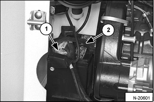
Remove the battery from the loader.
Remove the battery hold down clamp (Item 2)
Always clean the battery terminals and cable ends when installing a new or used battery [Figure PM-54]
When installing the battery in the loader, do not touch any metal parts with the battery terminals.
Connect the negative (-) cable last to prevent sparks. Connect and tighten the battery cables.
Close the rear door before operating the loader.
HYDRAULIC/HYDROSTATIC SYSTEM Checking And Adding Fluid
Use only recommended fluid in the hydraulic system. (See SKID STEER LOADER SPECIFICATIONS on Page SPEC-3.)
Stop the loader on a level surface. Lower the lift arms and tilt the Bob-Tach fully back.
Stop the engine.
Figure PM-55
Remove the screen [Figure PM-57] & clean with solvent as needed.
Install the fill cap.
Replacing Hydraulic/Hydrostatic Filter
For the correct service intervals (See SERVICE SCHEDULE on Page PM-7.)
Open the rear door.
Figure PM-58
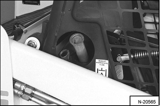
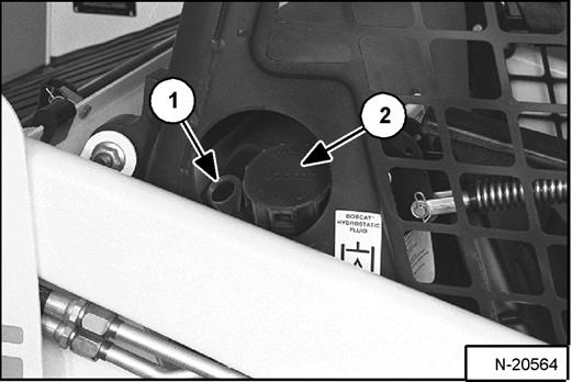
Remove the dipstick (Item 1) [Figure PM-55]. Check the fluid level.
Remove the fill cap (Item 2) [Figure PM-55]
Figure PM-56
Add the fluid as needed to bring the level to the top mark on the dipstick [Figure PM-56]. Do not fill above the top mark.
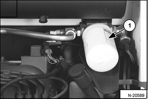
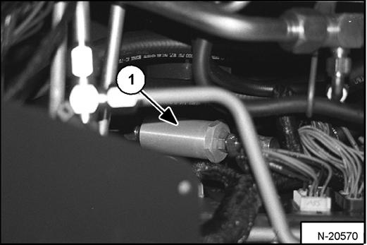
Remove the filter element (Item 1) [Figure PM-58]
Clean the surface of the filter housing where the seal contacts the housing.
Put clean oil on the seal of the new filter element.
Install and hand tighten the filter element.
Close the rear door before operating the loader.
HYDRAULIC/HYDROSTATIC SYSTEMS (CONT’D)
Replacing Hydraulic Fluid and Case Drain Filters
For the service interval (See SERVICE SCHEDULE on Page PM-7.)
The fluid must be replaced if it becomes contaminated or after major repairs. If the fluid is replaced, the hydrostatic filter and both case drain filters must be replaced.
Figure PM-59
Remove the reservoir fill cap (Item 1) [Figure PM-59]
Raise the operator cab. (See Raising The Operator Cab on Page PM-10.)
Figure PM-60
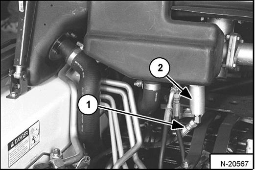
Disconnect the hose (Item 1) [Figure PM-60] from the case drain filter located on the reservoir. Use a cap on the hose to prevent leakage.
Remove the case drain filter (Item 2) [Figure PM-60]. Drain the fluid into a container.
Drain the fluid into a container and recycle or dispose in an environmentally safe manner.
Figure PM-61
Remove the left case drain filter (Item 1) [Figure PM-61] and drain the fluid into a container.
Recycle or dispose of the fluid in an environmentally safe manner.
Replace the hydraulic/hydrostatic filter element. (See HYDRAULIC/HYDROSTATIC SYSTEM on Page PM-30.)
Install new hydrostatic motor case drain filters (Item 2) [Figure PM-60] & (Item 1) [Figure PM-61] and reconnect the hoses.
Add the correct fluid to the reservoir until the fluid level is between the marks on the dipstick. DO NOT fill above the top mark on the dipstick.

Warning
Hydraulic fluid escaping under pressure can have sufficient force to enter a person’s body by penetrating the skin. This can cause serious injury and possible death if proper medical treatment by a physician familiar with this injury is not received immediately.
W-2145-0290
Warning
Always clean up spilled fuel or oil. Keep heat, flames, sparks or lighted tobacco away from fuel and oil. Failure to use care around combustibles can cause explosion or fire which can result in injury or death.
W-2103-1285
HYDRAULIC/HYDROSTATIC SYSTEMS (CONT’D)
Replacing Hydraulic Fluid and Case Drain Filters (Cont’d)
Lower the operator cab. (See Lowering The Operator Cab on Page PM-11.)
Start the engine and operate the loader hydraulic controls. Stop the engine and check for leaks.
Check the fluid level in the reservoir and add as needed.
Breather Cap
For the correct service interval. (See SERVICE SCHEDULE on Page PM-7.)
Raise the cab. (See Raising The Operator Cab on Page PM-10.)
NOTE: Be sure the rubber gasket (Item 2) is installed on the cap and the baffle washer (Item 3) [Figure PM-63] is installed over the opening of the hydraulic reservoir.
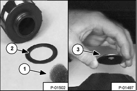
Install the breather cap.
Lower the cab. (See Lowering The Operator Cab on Page PM-11.)
Spark Arrestor Muffler
For service interval for cleaning the spark arrestor muffler
(See SERVICE SCHEDULE on Page PM-7.)
Do not operate the loader with a defective exhaust system.
Important
This loader is factory equipped with a U.S.D.A. Forestry Service approved spark arrestor muffler. It is necessary to do maintenance on this spark arrestor muffler to keep it in working condition. The spark arrestor muffler must be serviced by dumping the spark chamber every 100 hours of operation.
If this machine is operated on flammable forest, brush or grass covered land, it must be equipped with a spark arrestor attached to the exhaust system and maintained in working order. Failure to do so will be in violation of California State Law, Section 4442 PRC.
Make reference to local laws and regulations for spark arrestor requirements
I-2022-0595
Stop the engine. Open the rear door and raise the rear grill.
Warning
When the engine is running during service, the steering levers must be in neutral and the parking brake engaged. Failure to do so can cause injury or death.
W-2006-0284
Start the engine and run for about 10 seconds while a second person, wearing safety glasses, holds a piece of wood over the outlet of the muffler.

This will force contaminants out through the cleanout hole.
Stop the engine.
Install and tighten the plug.
Lower the rear grill and close the rear door.
Warning
When an engine is running in an enclosed area, fresh air must be added to avoid concentration of exhaust fumes. If the engine is stationary, vent the exhaust outside. Exhaust fumes contain odorless, invisible gases which can kill without warning.
W-2050-1285
Warning
Stop engine and allow the muffler to cool before cleaning the spark chamber. Wear safety goggles. Failure to obey can cause serious injury.
W-2011-1285
Warning
Never use machine in atmosphere with explosive dust or gases or where exhaust can contact flammable material. Failure to obey warnings can cause injury or death.
W-2068-1285
Tire Maintenance
Wheel Nuts
Figure PM-65
For the service interval to check the wheel nuts [Figure PM-65] (See SERVICE SCHEDULE on Page PM-7.).
When installing wheel nuts, tighten to 160 ft.-lb. (217 N•m) torque.
When checking wheel nut torque, set the torque wrench to 140 ft.-lb. (190 N•m) to prevent over-tightening.
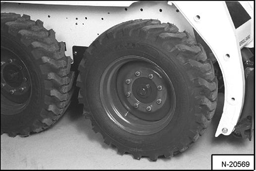
Rotating
Check the tires regularly for wear, damage and pressure. (See SKID STEER LOADER SPECIFICATIONS on Page SPEC-3 for the correct tire pressure.)
Figure PM-66
Rear tires usually wear faster than front tires. To keep tire wear even, move the front tires to the rear and rear tires to the front [Figure PM-66]
It is important to keep the same size tires on each side of the loader. If different sizes are used, each tire will be turning at a different rate and cause excessive wear. The tread bars of all the tires must face the same direction.
Recommended tire pressure must be maintained to avoid excessive tire wear and loss of stability and handling capability. Check for the correct pressure before operating the loader.
Mounting
Tires are to be repaired only by an authorized person using the proper procedures and safety equipment.
Tires and rims must always be checked for correct size before mounting. Check rim and tire bead for damage.
The rim flange must be cleaned and free of rust.
The tire bead and rim flange must be lubricated with a rubber lubricant before mounting the tire.
Avoid excessive pressure which can rupture the tire and cause serious injury or death.
During inflation of the tire, check the tire pressure frequently to avoid over inflation.
Warning
Do not inflate tires above specified pressure. Failure to use correct tire mounting procedure can cause an explosion which can result in injury or death.
W-2078-1285
Important
Inflate tires to the MAXIMUM pressure shown on the sidewall of the tire. DO NOT mix brands of tires used on the same loader.
I-2057-0794
FINAL DRIVE TRANSMISSION (CHAINCASE)
Checking And Adding Oil
The chaincase contains the final drive sprockets and chains. Use the same type of oil as the hydraulic/ hydrostatic system. (See SKID STEER LOADER SPECIFICATIONS on Page SPEC-3.)
Stop the loader on a level surface.
Stop the engine.
If oil can be reached with the tip of the your finger through the hole, the oil level is correct.
If the level is low, add oil through the check plug hole until the oil flows from the hole.
Install and tighten the plug.
Removing Oil From The Chaincase
Remove an environmentally safe manner.
Check the drain plug and replace as necessary.
Fan Gearbox
For the correct service interval (See SERVICE SCHEDULE on Page PM-7.)
Checking And Maintaining
Raise the operator cab. (See Raising The Operator Cab on Page PM-10.)
Figure PM-70
Remove the plug (Item 1) [Figure PM-70] to check the lubricant level.
If the level is low, add SAE 90W gear lubricant through the check plug hole until lubricant flows from the hole.
Install and tighten the plug.
Lower the operator cab. (See Lowering The Operator Cab on Page PM-11.)
DRIVE BELT Adjusting The Drive Belt
Stop the engine.
Open the rear door and disconnect the negative (-) cable from the battery.
Remove three belt shield fasteners and remove the belt shield.
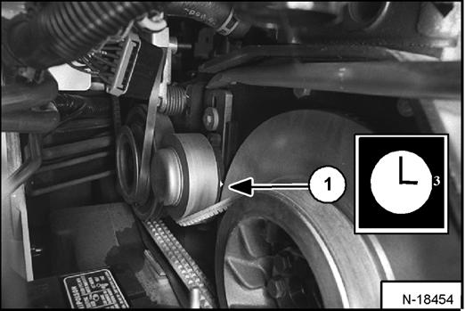
NOTE: Do not set the idler against the travel stop in the 3 o'clock position.
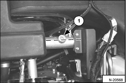
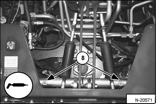
Tighten the mounting bolt (Item 1) [Figure PM-71] to 2528 ft.-lb. (34-38 N•m) torque.
Run the engine for a few minutes. Stop the engine and recheck the pointer position.
Readjust if necessary.
After the idler has been in service, readjust when the pointer reaches the 1 o'clock position.
Install the belt shield and fasteners.
Connect the negative (-) battery cable.
Close the rear door.
Replacing The Drive Belt
Follow the steps above to loosen the drive belt tensioner.
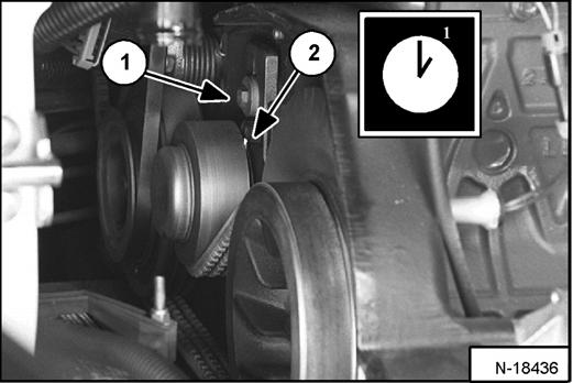
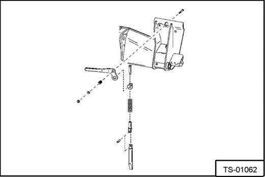
Remove the bolt (Item 1) [Figure PM-71] from the tensioner and remove the tensioner assembly.
Remove the fan drive belt.
Loosen the bolt (Item 1) [Figure PM-71] on the spring loaded drive idler.
NOTE: The pointer will be at the 1 o'clock position (Item 2) [Figure PM-71] when the belt tensioner is not under spring tension.
Remove the drive belt from the pump pulley and flywheel and remove the belt from the loader.
Install the new drive belt. Install the belt tensioner assembly.
Install the fan drive belt.
Adjust the drive belt, reinstall previously removed components and continue procedure from Adjusting The Drive Belt above.
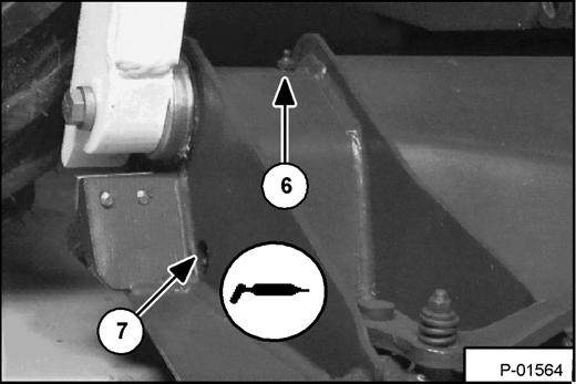
Push the idler pulley against the belt, using a pry bar [Figure PM-72]. The pointer will be at the 3 o'clock position (Item 1) [Figure PM-72] when the idler pulley is against the stop (maximum movement)
Raise the idler assembly slightly so that the pulley is operating on spring tension and not against the stop.
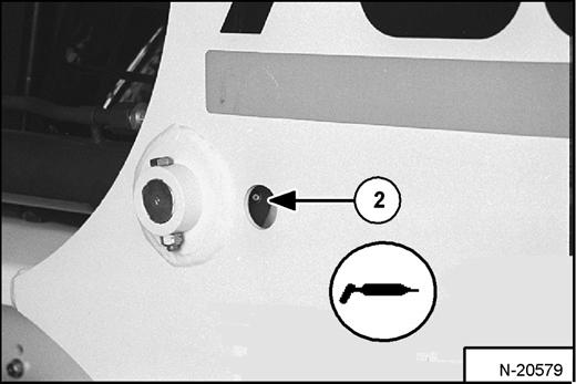
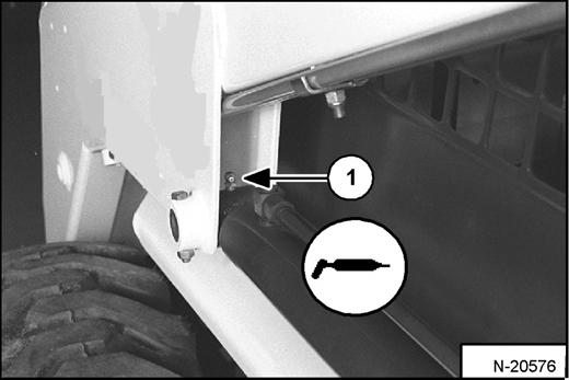
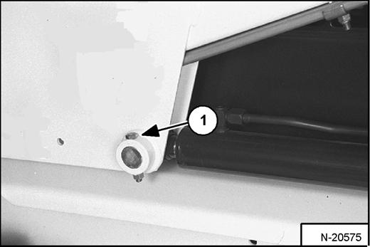
Lubrication Of The Bobcat Loader
Lubricate the loader as specified in the SERVICE SCHEDULE for the best performance of the loader. (See SERVICE SCHEDULE on Page PM-7.)
Record the operating hours each time you lubricate the Bobcat Loader.
Always use a good quality lithium based multi-purpose grease. Apply lubricant until extra grease shows.
Lubricate the following locations on the loader:
LUBRICATION OF THE BOBCAT LOADER (CONT’D)
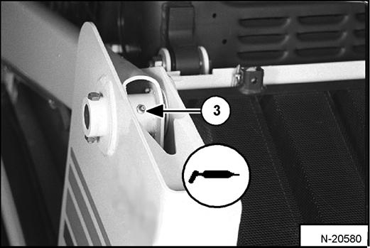
PIVOT PINS
Figure PM-80
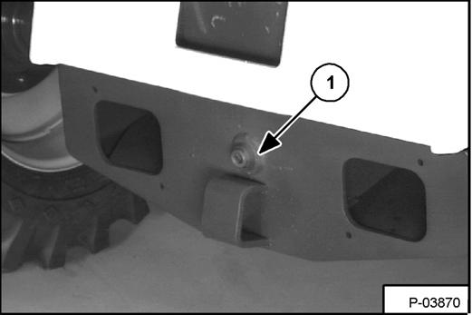
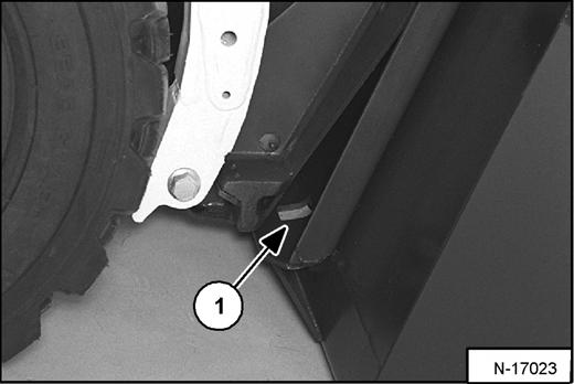
All lift arm and cylinder pivots have a large pin held in position with a retainer bolt and lock nut (Item 1) [Figure PM-80]
Check that the lock nuts are tightened to 18-20 ft.-lb. (2427 N•m) torque.
BOB-TACH
Inspection and Maintenance
Figure PM-81
Move the Bob-Tach levers to engage the wedges [Figure PM-81]. The levers and wedges must move freely.
The wedges must extend through the holes in the attachment mounting frame (Item 1) [Figure PM-81]
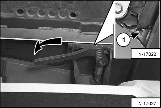
Warning
Bob-Tach wedges must extend through the holes in attachment. Lever(s) must be fully down and locked. Failure to secure wedges can allow attachment to come off and cause injury or death.
W-2102-0497
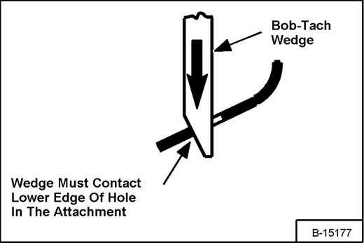
The spring loaded wedge (Item 1) [Figure PM-81] must contact the lower edge of the hole in the attachment (Item 1) [Figure PM-82] and [Figure PM-83].
If the wedge does not contact the lower edge of the hole [Figure PM-82] and [Figure PM-83], the attachment will be loose and can come off the Bob-Tach.
Inspect the mounting frame on the attachment and the Bob-Tach, linkages and wedges for excessive wear or damage [Figure PM-84]. Replace any parts that are damaged, bent, or missing. Keep all fasteners tight.
Look for cracked welds. Contact your Bobcat dealer for repair or replacement parts.
Lubricate the wedges. (See SERVICE SCHEDULE on Page PM-7.) (See LUBRICATION OF THE BOBCAT LOADER on Page PM-38.)