3 minute read
SEAT BAR RESTRAINT SYSTEM ADVANCED CONTROL SYSTEM (ACS) AND ADVANCED HAND CONTROLS (AHC)


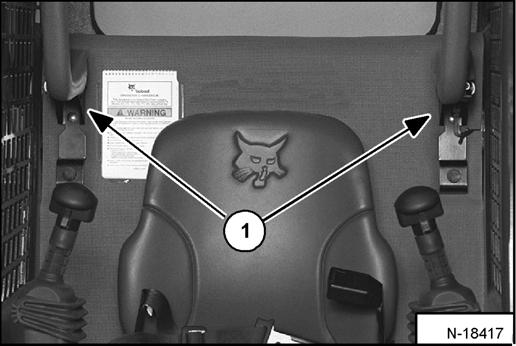
Figure PM-19
The seat bar restraint system [Figure PM-19] has a pivoting seat bar with arm rests.
The operator controls the use of the seat bar. The seat bar in the down position helps to keep the operator in the seat.
When the seat bar is down, engine running and the PRESS TO OPERATE LOADER Button is pressed, the lift, tilt, and traction drive functions can be operated.
When the seat bar is up, the lift, tilt and traction drive functions are deactivated.
Inspecting the Seat Bar
Sit in the seat. Turn the key ON (Standard Panel), press RUN /ENTER Button (Deluxe Panel), lower the seat bar and press the PRESS TO OPERATE LOADER Button.
Move each hand control back and forth. You should hear the zip-zip sound of the lift and tilt actuators moving the control valve spools (under the seat).
Raise the seat bar fully. Move each hand control back and forth. There must be no zip-zip sound of the lift or tilt actuators. If either actuator makes a sound while the seat bar is raised, contact your dealer for service.
Maintaining the Seat Bar
See the SERVICE SCHEDULE in this manual and on the loader for correct service interval. (See SERVICE SCHEDULE on Page PM-7.)
Use compressed air to clean any debris or dirt from the pivot parts (Item 1) [Figure PM-19]. Do not lubricate. Inspect all mounting hardware. The correct bolt torque is 26 ft.-lb. (35 N•m).
If the seat bar system does not function correctly, replace parts that are worn or damaged. Use only genuine Bobcat replacement parts.
Warning
The seat bar system must deactivate the lift and tilt control functions when the seat bar is up. Service the system if hand controls do not deactivate.
W-2355-0799
BOBCAT INTERLOCK CONTROL SYSTEM (BICS)
Inspecting The BICS Controller
(Engine STOPPED - Key ON)
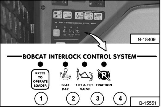
Figure PM-20
1.Sit in the operator's seat. Turn key ON (Standard Panel), press RUN / ENTER Button (Deluxe Panel, lower the Seat Bar and disengage the parking brake pedal. Press the PRESS TO OPERATE LOADER Button. Three BICS lights (Items 1, 2, & 3) [Figure PM-20] [PRESS TO OPERATE LOADER, SEAT BAR, and LIFT & TILT VALVE] on left instrument panel should be ON [Figure PM-20].
2.Raise the Seat Bar fully. All four BICS lights (Items 1, 2, 3, & 4) [Figure PM-20] [PRESS TO OPERATE LOADER, SEAT BAR, LIFT & TILT VALVE and TRACTION*] on left instrument panel should be OFF [Figure PM-20].
NOTE: Record what lights are blinking (if any) and the number of light flashes. (See BICS™ SYSTEM on Page SA-3.)
Inspecting Deactivation Of The Auxiliary Hydraulics System
(Engine STOPPED - Key ON)
3.Sit in the operator's seat, lower the Seat Bar, and press the PRESS TO OPERATE LOADER Button. Press the auxiliary hydraulics FLOW Button. The auxiliary FLOW Button light will come ON. Raise the Seat Bar. The light should be OFF.
Inspecting The Seat Bar Sensor
(Engine RUNNING)
4.Sit in the operator's seat, lower the seat bar, engage the parking brake pedal and fasten the seat belt.
5.Start the engine and operate at low idle. Press the PRESS TO OPERATE LOADER Button. While raising the lift arms, raise the Seat Bar fully. The lift arms should stop. Repeat using the tilt function.
Inspecting The Traction Lock
(Engine RUNNING)
6.Fasten the seat belt, disengage the parking brake pedal, press the PRESS TO OPERATE LOADER Button and raise the Seat Bar fully. Move the steering levers slowly forward and backward. The TRACTION lock should be engaged. Lower the Seat Bar. Press the PRESS TO OPERATE LOADER Button.
7.Engage the parking brake pedal and move the steering levers slowly forward and backward. The TRACTION lock should be engaged.
NOTE: *The TRACTION light on the left instrument panel will remain OFF until the engine is started, the PRESS TO OPERATE LOADER Button is pressed and the parking brake is disengaged.
Warning
AVOID INJURY OR DEATH
The Bobcat Interlock Control System (BICS) must deactivate the lift, tilt and traction drive functions. If it does not, contact your dealer for service. DO NOT modify the system.
W-2151-0394
Inspecting The Lift Arm By-Pass Control
8.Raise the lift arms 6 feet (2 meters) off the ground. Stop the engine.
Turn the lift arm by-pass control knob clockwise 1/4 turn. Pull up and hold the lift arm by-pass control knob until the lift arms slowly lower.