11 minute read
MAINTENANCE SAFETY


Instructions are necessary before operating or servicing machine. Read and understand the Operation & Maintenance Manual, Operator’s Handbook and signs (decals) on machine. Follow warnings and instructions in the manuals when making repairs, adjustments or servicing. Check for correct function after adjustments, repairs or service. Untrained operators and failure to follow instructions can cause injury or death. W-2003-0903
Safety Alert Symbol: This symbol with a warning statement, means: “Warning, be alert! Your safety is involved!” Carefully read the message that follows.
Never service the Bobcat SkidSteer Loader without instructions.
Use the correct procedure to lift or lower operator cab.
Have good ventilation when welding or grinding painted parts.
Wear dust mask when grinding painted parts. Toxic dust and gas can be produced. Avoid exhaust fume leaks which can kill without warning. Exhaust system must be tightly sealed.
Disconnecting or loosening any hydraulic tubeline, hose, fitting, component or a part failure can cause lift arms to drop. Do not go under lift arms when raised unless supported by an approved lift arm support device. Replace it if damaged.
Stop, cool and clean engine of flammable materials before checking fluids.
Never service or adjust loader with the engine running unless instructed to do so in the manual.
Avoid contact with leaking hydraulic fluid or diesel fuel under pressure. It can penetrate the skin or eyes.
Never fill fuel tank with engine running, while smoking or when near open flame.
Keep body, jewelry and clothing away from moving parts, electrical contact, hot parts and exhaust. Wear eye protection to guard from battery acid, compressed springs, fluids under pressure and flying debris when engines are running or tools are used. Use eye protection approved for type of welding. Keep rear door closed except for service. Close and latch door before operating the loader.
Never work on loader with lift arms up unless lift arms are held by an approved lift arm support device. Replace if damaged. Never modify equipment or add attachments not approved by Bobcat Company.
WRONG B-6589
Lead-acid batteries produce flammable and explosive gases. Keep arcs, sparks, flames and lighted tobacco away from batteries.
Batteries contain acid which burns eyes or skin on contact. Wear protective clothing. If acid contacts body, flush well with water. For eye contact flush well and get immediate medical attention.
Maintenance procedures which are given in the Operation & Maintenance Manual can be performed by the owner/ operator without any specific technical training. Maintenance procedures which are not in the Operation & Maintenance Manual must be performed ONLY BY QUALIFIED BOBCAT SERVICE PERSONNEL. Always use genuine Bobcat replacement parts. The Service Safety Training Course is available from your Bobcat dealer.
Cleaning and maintenance are required daily. MSW08-0805

Service Schedule
Chart
Maintenance work must be done at regular intervals. Failure to do so will result in excessive wear and early failures. The service schedule is a guide for correct maintenance of the Bobcat Loader.
Warning
Engine Oil
Instructions are necessary before operating or servicing machine. Read and understand the Operation & Maintenance Manual, Operator’s Handbook and signs (decals) on machine. Follow warnings and instructions in the manuals when making repairs, adjustments or servicing. Check for correct function after adjustments, repairs or service. Untrained operators and failure to follow instructions can cause injury or death.
Service Schedule
Check the oil level and add as needed. Do not overfill.
Engine Air Filter and Air SystemCheck display panel. Service only when required. Check for leaks and damaged components.
Engine Cooling SystemClean debris from oil cooler, radiator & grill. Check coolant level COLD and add premixed coolant as needed.
Fuel Filter Remove the trapped water.
Lift Arms, Cylinders, Bob-Tach Pivot Pins and Wedges
Tires
Seat Belt, Seat Bar, Control Interlocks, Seat Belt Retractors
Lubricate with multi-purpose lithium based grease.
Check for damaged tires and correct air pressure. Inflate to MAXIMUM pressure shown on sidewall of tire.
Check the condition of seat belt. Check the sear bar and control interlocks for correct operation. Clean dirt and debris from moving parts. Clean or replace seat belt retractors as needed.
Bobcat Interlock Control Systems (BICS) Check that four BICS indicator lights and functions are activated. See details in this Manual.
Safety Signs and Safety TreadsCheck for damaged signs (decals) and safety treads. Replace any signs or safety treads that are damaged or worn.
Operator Cab Check the fastening bolts, washers and nuts. Check the condition of the cab. Indicators and Lights Check for correct operation of all indicators and lights.
Heater and A/C Filters (If Equipped) Clean or replace filters as needed.
Hydraulic Fluid, Hoses and Tubelines
Final Drive Trans. (Chaincase), Foot Pedals, Hand Controls or Steering Levers
Check fluid level and add as needed. Check for damage and leaks. Repair or replace as needed.
Check oil level and add oil as needed. Check for correct operation. Repair or adjust as needed.
Parking Brake Check operation.
Wheel Nuts
Check for loose wheel nuts and tighten to correct torque. (See TIRE MAINTENANCE on Page PM-34.)
Spark Arrestor Muffler Clean the spark chamber.
Battery Check cables, connections and electrolyte level. Add distilled water as needed.
Steering Lever Pivots Grease fittings.
Fuel Filter Replace filter element.
Engine/Hydro. Drive BeltCheck for wear or damage.
Fan Drive Gearbox Check gear lube level. Add as needed.
Alternator Belt Check condition and tension. Adjust or replace as needed.
Bobcat Interlock Control System (BICS) Check the function of the lift arm by-pass control.
Engine Oil and Filter Replace oil and filter. Use CD or better grade oil and Bobcat filter. ✵
Hydraulic/Hydrostatic Filter, Reservoir Breather Cap Replace the hydrostatic filter, steering valve filter and the reservoir breather cap.
Final Drive Trans. (Chaincase)Replace the fluid.
Hydraulic Reservoir Replace the fluid.
Case Drain Filters Replace the filters.
Coolant Replace the coolant Every 2 years
■ Or every 12 months.
❏ Check every 8-10 hours for the first 24 hours; then at 50 hour intervals.
❍ Inspect new belt after first 50 hours.
✵ First oil and filter change must occur at 50 hours; 250 hours thereafter.
▼ Replace the filter element after the first 50 hours and when the transmission warning light comes ON.
W-2003-0903
Lift Arm Support Device
Maintenance and service work can be done with the lift arms lowered. If the lift arms are raised, use the following procedures to engage and disengage an approved lift arm support device:
Warning
Never work on a machine with the lift arms up unless the lift arms are secured by an approved lift arm support device. Failure to use an approved lift arm support device can allow the lift arms or attachment to fall and cause injury or death.
W-2059-0598
Warning
Service lift arm support device if damaged or if parts are missing. Using a damaged lift arm support or with missing parts can cause lift arms to drop causing injury or death.
W-2271-1197
Engaging The Lift Arm Support Device
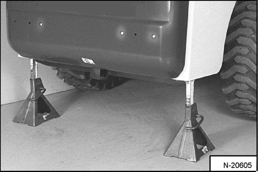
Figure PM-1
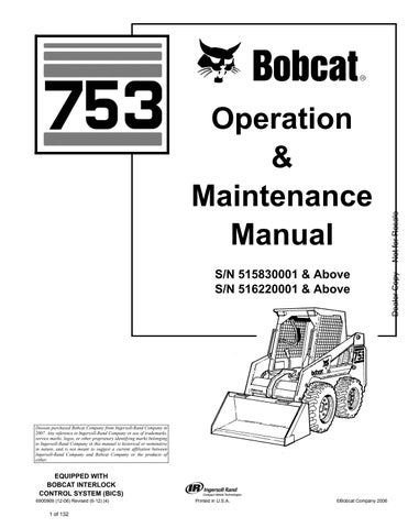
Install jackstands under the rear of the loader frame (Inset) [Figure PM-1]
Disconnect the spring from the lift arm support device retaining pin (Item 1) [Figure PM-1]. Support the lift arm support device (Item 2) [Figure PM-1] with your hand and remove the retaining pin.
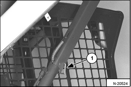
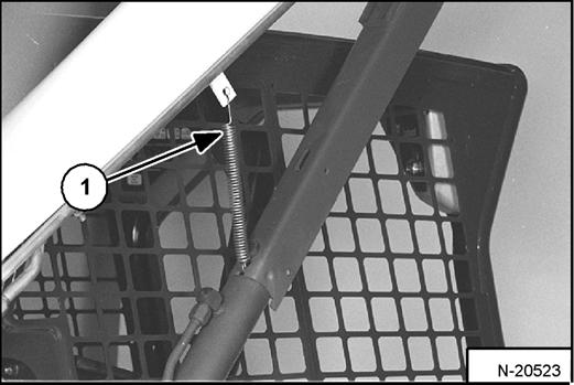
Lower the lift arm support device on top of the lift cylinder. Hook the free end of the spring (Item 1) [Figure PM-2] to the lift arm support device so there will be no interference with the support device engagement.
With the operator in the seat, seat belt fastened and seat bar lowered, start the engine.
Press the PRESS TO OPERATE LOADER button.
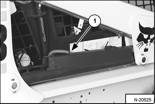
Raise the lift arms, until the lift arm support device drops onto the lift cylinder rod [Figure PM-3].
Lower the lift arms slowly until the support device is held between the lift arm and the lift cylinder. Stop the engine. Raise the seat bar and move pedals or the hand controls until both pedals lock.
Install pin (Item 1) [Figure PM-3] into the rear of the lift arm support device below the cylinder rod.
LIFT ARM SUPPORT DEVISE (CONT’D)
Disengaging The Lift Arm Support Device
Remove the pin from the lift arm support device.
Figure PM-4
Connect the spring (Item 1) [Figure PM-4] from the lift arm support device to the bracket below the lift arms.
With the operator in the seat, seat belt fastened and seat bar lowered, start the engine.
Press the PRESS TO OPERATE LOADER button.
Raise the lift arms a small amount and the spring will lift the support device off the lift cylinder rod. Lower the lift arms. Stop the engine.
Raise the seat bar and move pedals (or hand controls) until both pedals lock.
Disconnect the spring from the bracket.
Figure PM-5
HEATER Filter Cleaning and Maintenance
The heater filters require regular inspection and maintenance. (See SERVICE SCHEDULE on Page PM7.)
Filters
Figure PM-6
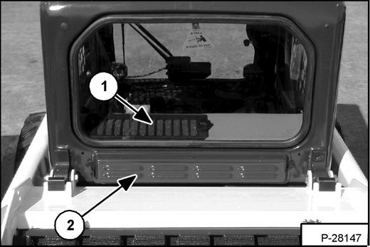
The Fresh Air Filter is located below the rear window of the cab (Item 1) [Figure PM-6]
Remove the bolts and remove the filter housing.
Shake the filter or use low air pressure to remove dirt.
Reinstall the filter and housing.
The Recirculation Filter is located in front of the rear window inside the cab (Item 2) [Figure PM-6]

Remove the clamping knobs, grill and filter.
Clean the filter with water and mild detergent. Reinstall the filter.
Troubleshooting
If the fan does not run, check the fuse. (See ELECTRICAL SYSTEM on Page PM-27.)
Raise the support device into storage position and insert pin (Item 1) [Figure PM-5] through lift arm support device (Item 2) [Figure PM-5] and bracket. Connect spring to pin.
Remove jackstands.
Operator Cab
The Bobcat Loader has an operator cab (ROPS and FOPS) as standard equipment to protect the operator from rollover and falling objects. Check with your dealer if the operator cab has been damaged. The seat belt must be worn for roll over protection.
ROPS/FOPS - Roll Over Protective Structure per SAE J1040 and ISO 3471, and Falling Object Protective Structure per SAE J1043 and ISO 3449, Level I. Level II is available.
Level I - Protection from falling bricks, small concrete blocks, and hand tools encountered in operations such as highway maintenance, landscaping, and other construction site services.
Level II - Protection from falling trees, rocks; for machines involved in site clearing, overhead demolition or forestry.
Raising The Operator Cab
Always stop the engine before raising or lowering the cab.
Stop the loader on a level surface. Lower the lift arms. If the lift arms must be up while raising the operator cab, install the lift arm support device. (See LIFT ARM SUPPORT DEVICE on Page PM-8.)
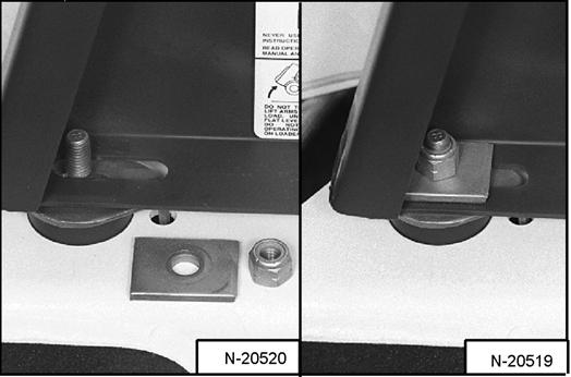
Loosen the nut (both sides) at the front corner of the operator cab [Figure PM-8]
Remove the nuts and plates [Figure PM-8] (both sides).
OPERATOR CAB (CONT’D)
Advanced Control System (ACS) and Advanced Hand Control (AHC)
Lowering The Operator Cab
Always stop the engine before raising or lowering the cab.

Figure PM-10
Warning
Never modify operator cab by welding, grinding, drilling holes or adding attachments unless instructed to do so by Bobcat Company. Changes to the cab can cause loss of operator protection from rollover and falling objects, and result in injury or death.
W-2069-0200
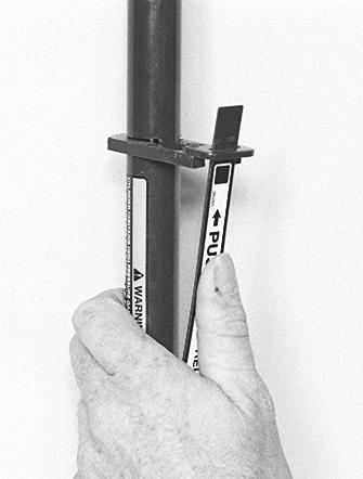
Pull down on the bottom of the operator cab until it stops at the latching mechanism [Figure PM-10]
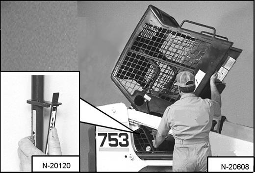
Figure PM-11
N-20120
Support the cab and release the latching mechanism [Figure PM-11]. Remove your hand from the latching mechanism when the cab is past the latch stop.
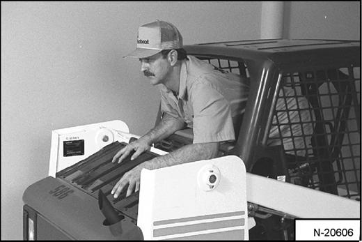
Use both hands to lower the cab all the way down.
NOTE: The weight of the cab increases when equipped with options and accessories such as cab door, heater, air-conditioning, etc. In these cases, the cab may need to be raised slightly from the latch to be able to release the latch.
OPERATOR CAB (CONT’D)
Lowering The Operator Cab (Cont’d)
Warning
PINCH POINT CAN CAUSE INJURY
Remove your hand from the latching mechanism when the cab is past the latch stop.
W-2469-0803
Figure PM-12
Install the plates and nuts [Figure PM-12] (both sides).
Tighten the nuts to 40-50 ft.-lb. (54-68 N•m) torque.
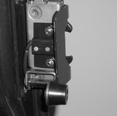
Cab Door Sensor (If Equipped)
Figure PM-13
A decal is located on the latch mechanism (Item 2) [Figure PM-13].
The LIFT & TILT VALVE light (Item 3) [Figure PM-13] will be ON when the door is closed and the PRESS TO OPERATE LOADER BUTTON is presses.
*The Cab Door Sensor Kit can be installed on early model cab doors. See you Bobcat dealer.
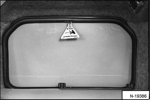
Emergency Exit
The front opening on the operator cab and rear window provide exits.
Rear Window (If Equipped)
Later model cab doors* have a sensor (Item 1) [Figure PM-13] installed which deactivates the lift and tilt valves when the door is open.

Push the rear window out of the rear of the operator cab.
Exit through the rear of the operator cab [Figure PM-15]
OPERATOR CAB (CONT’D)
Emergency Exit (Cont’d)
Front Door (If Equipped)
Figure PM-16
NOTE: When an Operator Cab Enclosure Kit is installed, the window of the front door can be used as an emergency exit. [Figure PM-16]
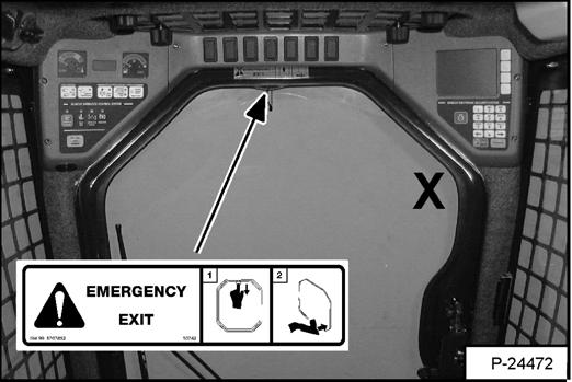
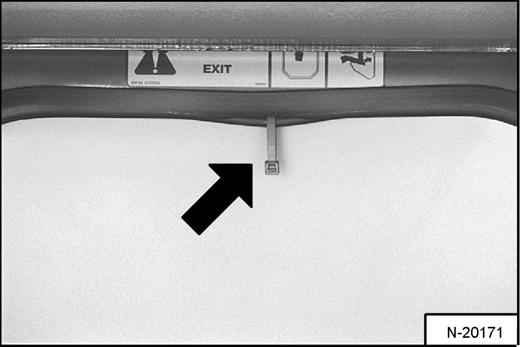
Pull the plastic loop at the top of the window in the front door to remove the rubber cord [Figure PM-16]
Figure PM-17
Push the window out with your foot [Figure PM-17] at any corner of the window.
Exit through the front door.
SEAT BAR RESTRAINT SYSTEM (FOOT PEDALS)
The seat bar restraint system has a pivoting seat bar with arm rests and hydraulic valve spool interlocks for the lift and tilt functions.
The operator controls the use of the seat bar. The seat bar in the down position helps to keep the operator in the seat.
The spool interlocks require the operator to lower the seat bar in order to operate the foot pedal controls (If equipped).
When the seat bar is down, the PRESS TO OPERATE LOADER Button is activated and the engine is running, the lift, tilt, and traction drive functions can be operated.
When the seat bar is up, the lift and tilt control pedals are locked when returned to the NEUTRAL position.
Inspecting the Seat Bar
Sit in the seat and fasten the seat belt. Engage the parking brake. Pull the seat bar all the way down. Start the engine. Press the PRESS TO OPERATE LOADER Button. Operate each foot pedal to check that both the lift and tilt functions operate correctly. Raise the lift arms until the attachment is about 2 feet (600 mm) off the ground.
Raise the seat bar. Try to move each foot pedal. Pedals must be firmly locked in the NEUTRAL position. There must be no motion of the lift arms or tilt (attachment) when the controls are moved.
Pull the seat bar down, press the PRESS TO OPERATE LOADER Button, lower the lift arms. Operate the lift control. While the lift arms are going up, raise the seat bar. The lift arms must stop.
Lower the seat bar, press the PRESS TO OPERATE LOADER Button, lower the lift arms and put the attachment flat on the ground. Stop the engine. Raise the seat bar and operate the foot pedals to be sure that the pedals are firmly locked in the NEUTRAL position. Unfasten the seat belt.
Maintaining the Seat Bar
See the SERVICE SCHEDULE in this manual and on the loader for correct service interval. (See SERVICE SCHEDULE on Page PM-7.)
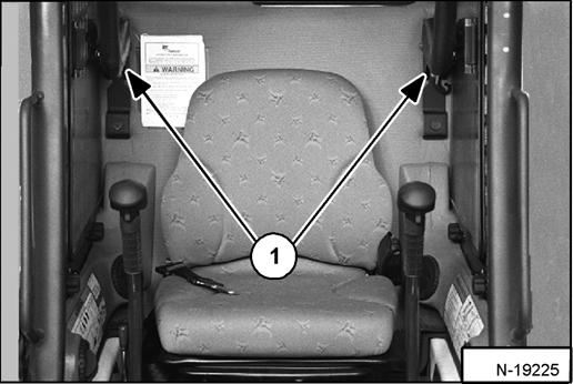
Figure PM-18
Use compressed air to clean any debris or dirt from the pivot points (Item 1) [Figure PM-18]. Do not lubricate. Inspect all mounting hardware. The correct bolt torque is 26 ft.-lb. (35 N•m).
If the seat bar system and hydraulic valve spool interlocks do not function correctly check all electrical wiring and connections. Replace parts that are worn or damaged. Use only genuine Bobcat replacement parts.
Warning
AVOID INJURY OR DEATH
The Seat Bar System must lock the lift and tilt foot pedals or hand controls in neutral when the Seat Bar is up. Service the system if controls do not lock correctly.
W-2263-0597