8 minute read
BOBCAT INTERLOCK CONTROL SYSTEM (BICS) (CONT’D)


Inspecting Deactivation Of Lift And Tilt Functions (AHC & ACS)
9.Sit in the operator's seat and fasten the Seat Belt. Lower the Seat Bar, start the engine and press the PRESS TO OPERATE LOADER Button.
10.Raise the lift arms about 6 feet (2 meters) off the ground.
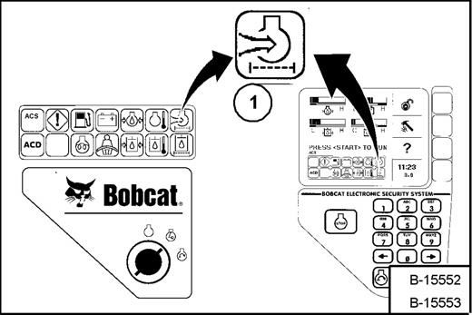
11.Turn key OFF (Standard Panel), press the STOP Button (Deluxe Panel, and wait for the engine to come to a complete stop.
12.Turn key ON (Standard Panel), press RUN/ENTER Button (Deluxe Panel. Press the PRESS TO OPERATE LOADER Button, move the left hand control toward the operator. The lift arms should not lower.
13.Move the right hand control away from the operator. The bucket (or attachment) should not tilt forward.
Opening And Closing The Rear Door
Warning
AVOID INJURY OR DEATH
Never service or adjust the machine when the engine is running unless instructed to do so in the manual.
Warning
Keep the rear door closed when operating the machine. Failure to do so could seriously injure a bystander.
W-2020-1285
Adjusting The Rear Door
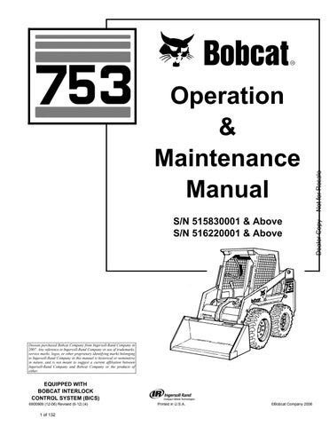
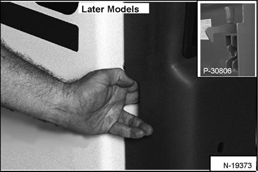
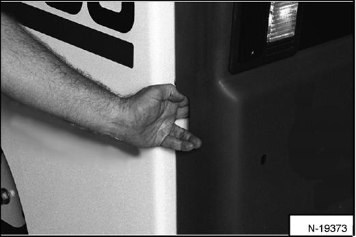
Reach into the slot in the rear door and pull the latch handle [Figure PM-21] & [Figure PM-22]
Pull the rear door open.
Move the door stop into the engaged position (Item 1) [Figure PM-22] to hold the door open.
Move the door stop up (Item 2) [Figure PM-22] to disengage the door stop and allow the door to close.
Close the door.
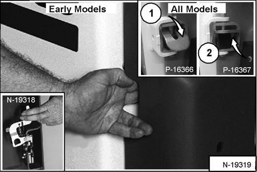
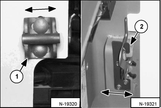
The door latch catch (Item 1) [Figure PM-23] & [Figure PM-24] can be adjusted side to side for alignment with the door latch mechanism.
Early Models Only - The door latch mechanism (Item 2) [Figure PM-24] can be adjusted backward or forward for alignment with the door catch.
Close the rear door before operating the loader.

Figure PM-25
Open the rear door [Figure PM-25]
Figure PM-26
Raise the rear grill [Figure PM-26]
The rear grill is held open by a cylinder (Item 1) [Figure PM-26].
Air Cleaner Service
Replacing Filter Element
Figure PM-27
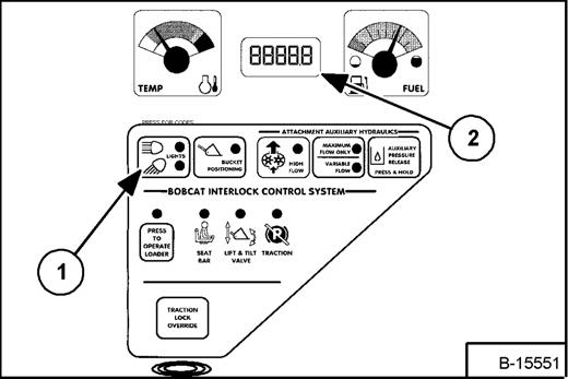
It is important to change the air filter element only when the Air Cleaner Icon in the right panel is ON (Item 1) [Figure PM-27] and you hear three beeps from the alarm.
Replace the inner filter every third time the outer filter is replaced or (See Replacing Filter Element on Page PM19.)
Press and hold the LIGHT Button (Item 1) [Figure PM28] for two seconds.
If the filter element needs replacement, the CODE [0117] (Air Filter Plugged) will show in the HOURMETER / CODE DISPLAY (Item 2) [Figure PM-28]
AIR CLEANER SERVICE (CONT’D)
Outer Filter
Figure PM-29
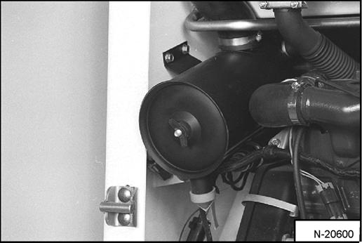
Remove the wing nut and remove the dust cover [Figure PM-29].
Figure PM-30
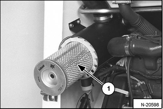
Remove the wing nut and remove the outer filter element (Item 1) [Figure PM-30].
NOTE: Make sure all sealing surfaces are free of dirt and debris.
Install a new outer element.
Install the dust cover and the wing nut [Figure PM-29].

Check the air intake hose and the air cleaner housing for damage. Make sure all connections are tight.
Inner Filter
Only replace the inner filter element under the following conditions:
•Replace the inner filter element every third time the outer filter is replaced.
•After the outer element has been replaced, start the engine and run at full RPM. If the HOURMETER / CODE DISPLAY shows [01-17] (Air Filter Plugged), replace the inner filter element.
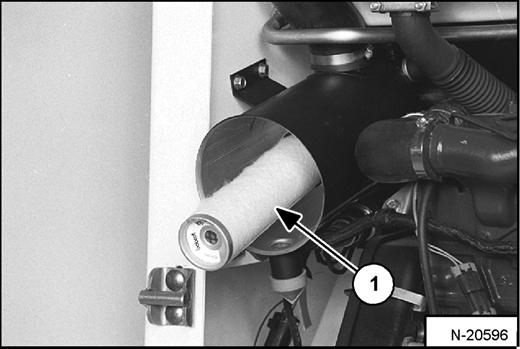
Remove the wing nut and remove the inner filter element (Item 1) [Figure PM-31]
NOTE: Make sure all sealing surfaces are free of dirt and debris.
Install the new inner element.
Install the outer element.
Fuel System
Fuel Specifications
Use only clean, high quality diesel fuel, Grade No. 2 or Grade No. 1.
The following is one suggested blending guideline which should prevent fuel gelling problems:
See your fuel supplier for local recommendations.
Filling The Fuel Tank
Warning
Stop and cool the engine before adding fuel. NO SMOKING! Failure to obey warnings can cause an explosion or fire.
W-2063-0887
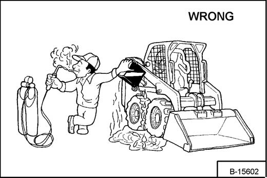
Use a clean, approved safety container to add fuel of the correct specifications. Add fuel only in an area that has free movement of air and no open flames or sparks. NO SMOKING! [Figure PM-34]
Install and tighten the fuel fill cap [Figure PM-33].

Fuel Filter
See the SERVICE SCHEDULE for the service interval when to remove the water from the fuel filter. (See SERVICE SCHEDULE on Page PM-7.)
Remove the fuel fill cap (Item 1) [Figure PM-33]
Warning
Always clean up spilled fuel or oil. Keep heat, flames, sparks or lighted tobacco away from fuel and oil. Failure to use care around combustibles can cause explosion or fire which can result in injury or death.
W-2103-1285
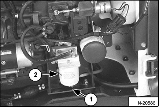
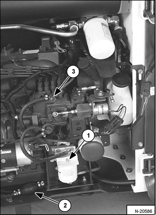
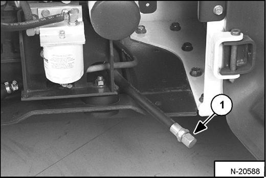
Loosen the drain (Item 1) [Figure PM-35] at the bottom of the filter element to drain water from the filter.
See the SERVICE SCHEDULE for the service interval when to replace the fuel filter. (See SERVICE SCHEDULE on Page PM-7.)
Remove the filter element (Item 2) [Figure PM-35].
Clean the area around the filter housing.
Put oil on the seal of the new filter element.
Install the fuel filter, and hand tighten.
Remove the air from the fuel system. (See Removing Air From The Fuel System on Page PM-22.)
FUEL SYSTEM (CONT’D)
Removing Air From The Fuel System
After replacing the fuel filter element or when the fuel tank has run out of fuel, the air must be removed from the fuel system before starting the engine.
Warning
Diesel fuel or hydraulic fluid under pressure can penetrate skin or eyes, causing serious injury or death. Fluid leaks under pressure may not be visible. Use a piece of cardboard or wood to find leaks. Do not use your bare hand. Wear safety goggles. If fluid enters skin or eyes, get immediate medical attention from a physician familiar with this injury.
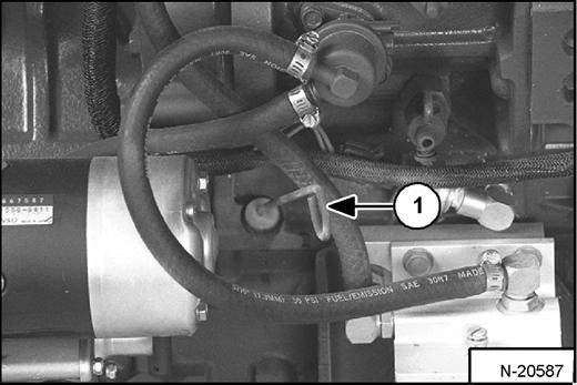
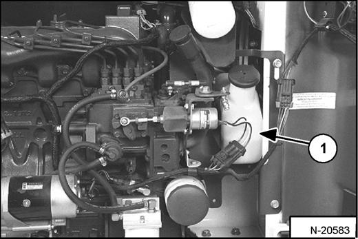
Close the fuel filter vent (Item 1) [Figure PM-36]
Open the injection pump vent (Item 3) [Figure PM-36].
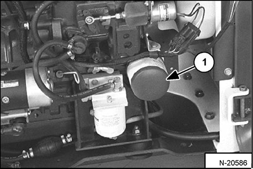
Operate the hand pump (priming bulb) (Item 2) [Figure PM-36] until the pump feels solid.
Tighten the injection pump vent (Item 3) [Figure PM-36]
Start the engine. It may be necessary to open the vent plug (at the fuel injection pump) briefly until the engine runs smoothly.
Open the fuel filter vent (Item 1) [Figure PM-36]
Operate the hand pump (priming bulb) (Item 2) [Figure PM-36] until fuel flows from the vent with no air bubbles.
Engine Lubrication System
Checking Engine Oil
Check the engine oil level every day before starting the engine for the work shift.
Remove the drain plug (Item 1) [Figure PM-38]
Drain the oil into a container and recycle or dispose of used oil in an environmentally safe manner.
Open the rear door and remove the dipstick (Item 1) [Figure PM-37]
Keep the oil level between the marks on the dipstick.
Use a good quality motor oil that meets API Service Classification of CD or better (See Oil Chart below).
Oil Chart
Remove the oil filter (Item 1) [Figure PM-39]
Clean the filter housing surface.
Put clean oil on the new oil filter gasket.
Install the filter and hand tighten.
Install and tighten the drain plug.
Replacing Oil And Filter
See the SERVICE SCHEDULE for the service interval for replacing the engine oil and filter. (See SERVICE SCHEDULE on Page PM-7.)
Run the engine until it is at operating temperature. Stop the engine.
Open the rear door.
ENGINE LUBRICATION SYSTEM (CONT’D)
Figure PM-40
Remove the filler cap (Item 1) [Figure PM-40]
Put oil in the engine. [Figure PM-40] (See Capacities: on Page SPEC-5.) (See Oil Chart on Page PM-23.)
Start the engine and let it run for several minutes.
Stop the engine.
Check for leaks at the oil filter and check the oil level.
Figure PM-41
Add oil as needed if it is not at the top mark (Item 1) [Figure PM-41] on the dipstick.
Warning
Always clean up spilled fuel or oil. Keep heat, flames, sparks or lighted tobacco away from fuel and oil. Failure to use care around combustibles can cause explosion or fire which can result in injury or death.
W-2103-1285
Engine Cooling System
Check the cooling system every day to prevent overheating, loss of performance or engine damage.
Warning
Wear safety glasses to prevent eye injury when any of the following conditions exist:
•When fluids are under pressure.
•Flying debris or loose material is present.
•Engine is running.
•Tools are being used.
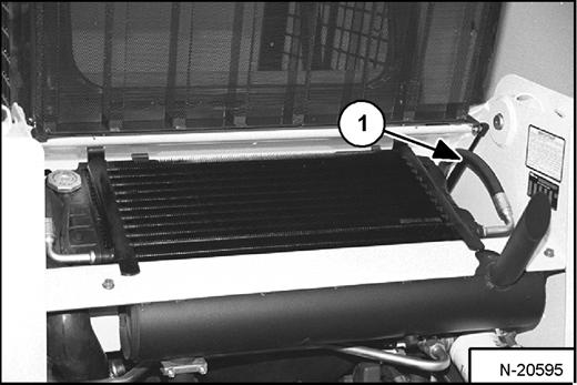
Cleaning The Cooling System
Raise the rear grill.
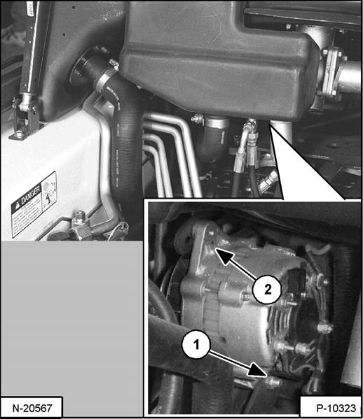
Figure PM-42
Use air pressure or water pressure to clean the top of the oil cooler [Figure PM-42]
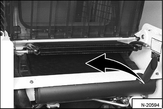

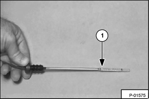
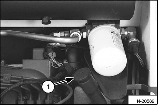
Figure PM-43
Check cooling system for leaks.
ENGINE COOLING SYSTEM (CONT’D)
Checking The Coolant Level
Open the rear door.
Figure PM-44
Check the coolant level in the coolant recovery tank (Item 1) [Figure PM-44]
The coolant level must be between the MIN and MAX marks on the coolant recovery tank when the engine is cold.
Important
AVOID ENGINE DAMAGE
Always use the correct ratio of water to antifreeze.
Too much antifreeze reduces cooling system efficiency and may cause serious premature engine damage.
Too little antifreeze reduces the additives which protect the internal engine components; reduces the boiling point and freeze protection of the system.
Always add a premixed solution. Adding full strength concentrated coolant can cause serious premature engine damage.
I-2124-0497
Replacing The Coolant
Warning
AVOID BURNS
Do not remove radiator cap when the engine is hot. You can be seriously burned.
W-2070-1203
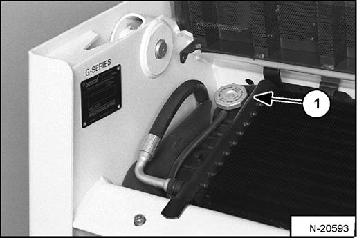
Open the rear door. Open the rear grill.
Figure PM-45
Remove the radiator cap (Item 1) [Figure PM-45]
Figure PM-46
Connect a hose to the engine block drain valve (Item 1) [Figure PM-46]
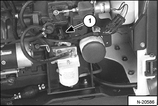
Open the drain valve and drain all of the coolant into a container. Dispose of used coolant in an environmentally safe manner.
Close the drain valve.
ENGINE COOLING SYSTEM (CONT’D)
Replacing The Coolant (Cont’d)
Mix the coolant in a separate container. (See Capacities: on Page SPEC-5.)
NOTE: The loader is factory filled with propylene glycol coolant (purple color). DO NOT mix propylene glycol with ethylene glycol.
Add premixed coolant, 47% water and 53% propylene glycol to the recovery tank if the coolant level is low.
One gallon and one pint (4,3 L) of propylene glycol mixed with one gallon (3,8 L) of water is the correct mixture of coolant to provide a -34°F (-37°C) freeze protection. Use a refractometer to check the condition of propylene glycol in your cooling system.
Fill the radiator with the premixed coolant. Install the radiator cap.
Add coolant to the recovery tank. The coolant level must be between the MIN and MAX marks on the coolant recovery tank.
Run the engine until it is at operating temperature.
Stop the engine.
Check the coolant level in the recovery tank when cool.
Add coolant to the recovery tank as needed.
Important
Avoid Engine Damage
Always use the correct ratio of water to antifreeze.
Too much antifreeze reduces cooling system efficiency and may cause serious premature engine damage.
Too little antifreeze reduces the additives which protect the internal engine components; reduces the boiling point and freeze protection of the system.
Always add a premixed solution. Adding full strength concentrated coolant can cause serious premature engine damage.
I-2124-0497
ALTERNATOR BELT Adjusting
Stop the engine.
Raise the operator cab. (See Raising The Operator Cab on Page PM-10.)
Loosen the alternator mounting bolt (Item 1) [Figure PM47]
Loosen the adjustment bolt (Item 2) [Figure PM-47]
Move the alternator until the belt has 5/16 inch (8,0 mm) movement at the middle of the belt span with 15 lb. (66 N•m) of force.
Tighten the adjustment bolt and mounting bolt.
Lower the operator cab.