13 minute read
STOPPING THE ENGINE


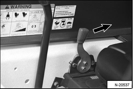
Figure OI-47
Pull the engine speed control fully backward [Figure OI47] to decrease the engine speed.
Turn the key switch to the STOP position [Figure OI-45] (Standard Panel) or press the STOP Button (Item 2) [Figure OI-46] (Deluxe Panel).
MONITORING THE DISPLAY PANEL
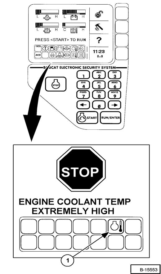
Figure OI-48
After the engine is running, frequently monitor the right instrument panel [Figure OI-48] (Standard Panel) and [Figure OI-49] (Deluxe Panel) for error conditions.

The associated Icon will be ON if there is an error condition.
EXAMPLE: Engine Coolant Temperature is High.
Standard Panel
The Engine Temperature Icon (Item 1) [Figure OI-48] will come ON.
Press and hold the LIGHTS Button for 2 seconds and one of the following SERVICE CODES will be displayed in the hourmeter / code display:
08-10 Engine Coolant Temperature High or
08-11 Engine Coolant Temperature Very High
Deluxe Panel
The Engine Temperature Icon (Item 1) [Figure OI-49] will be ON.
The SERVICE CODE will be in the hourmeter / code display (see above).
In addition, the Deluxe Panel display screen will describe the extreme condition that can cause damage to the engine or loader systems [Figure OI49]
WARNING AND SHUTDOWN:
When a WARNING condition exists, the associated Icon light will come ON and there will be 3 beeps from the alarm. Be aware that, if this condition is allowed to continue, there may be damage to the engine or loader hydraulic systems.
When a SHUTDOWN condition exists, the associated Icon light will come ON and there will be a continuous beep from the alarm and the monitoring system will automatically stop the engine in 10 seconds.
NOTE: The engine can be restarted to move or relocate the loader.
The SHUTDOWN feature is included with the Deluxe Right Panel or a Factory Option with the Standard Panel.
The SHUTDOWN feature is associated with the following Icons:
General Warning
Engine Oil Pressure
Engine Coolant Temperature
Hydraulic Oil Temperature
Hydrostatic Charge Pressure
Whenever STOP appears on the display screen, lower the lift arms all the way, put the attachment flat on the ground and stop the engine to prevent damage to the engine or loader systems.
Attachments And Buckets
NOTE: Warranty is void if non-approved attachments are used on the Bobcat Loader.
Warning
Never use attachments or buckets which are not approved by Bobcat Company. Buckets and attachments for safe loads of specified densities are approved for each model. Unapproved attachments can cause injury or death.
W-2052-0500 and avoiding machine damage, the attachment (or bucket) should handle a full load without going over the Rated Operating Capacity for the loader. Partial loads make steering more difficult.
The dealer can identify, for each model loader, the attachments and buckets approved by Bobcat. The buckets and attachments are approved for Rated Operating Capacity and for secure fastening to the BobTach.
The Rated Operating Capacity for this loader is shown on a decal in the operator cab. (See SKID STEER LOADER SPECIFICATIONS on Page SPEC-3.)
The Rated Operating Capacity is determined by using a standard dirt bucket, and material of normal density, such as dirt or dry gravel. If longer buckets are used, the load center moves forward and reduces the Rated Operating Capacity. If very dense material is loaded, the volume must be reduced to prevent overloading.
If a pallet fork attachment is used, the load center moves forward and reduces the Rated Operating Capacity.
Exceeding the Rated Operating Capacity [Figure OI-50] can cause the following problems:
•Steering the loader may be difficult.

•Tires will wear faster.
•There will be a loss of stability.
•The life of the Bobcat Loader will be reduced. Use the correct size bucket for the type and density of material being handled. For safe handling of materials
Maximum load to be carried when using a pallet fork is shown on a decal located on the pallet fork frame [Figure OI-51]

See your Bobcat Dealer for more information about pallet fork inspection, maintenance and replacement. See your Bobcat Loader dealer for Rated Operating Capacity when using a pallet fork and for other available attachments.
Warning
AVOID INJURY OR DEATH
Do not exceed Rated Operating Capacity (ROC). Excessive load can cause tipping or loss of control.
W-2053-0903
ATTACHMENTS AND BUCKETS (CONT’D)
Bob-Tach
Installing The Bucket Or Attachment
The Bob-Tach is used for fast changing of buckets and attachments. See the appropriate Attachment Operation & Maintenance Manual to install other attachments.
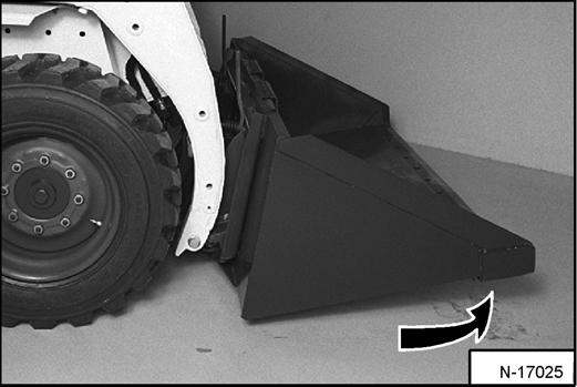
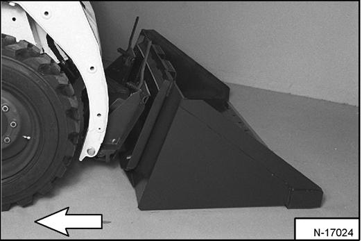
Tilt the Bob-Tach backward until the cutting edge of the bucket (or other attachment) is slightly off the ground [Figure OI-53].
Stop the engine and exit the loader.
Warning
Before you leave the operator’s seat:
•Lower the lift arms, put the attachment flat on the ground.
•Stop the engine.
•Engage the parking brake.
•Raise seat bar
•(Foot Pedal Controls Only) Move pedals until both lock.
•(Advanced Control System (ACS) and Advanced Hand Controls (AHC) Move the hydraulic controls to the NEUTRAL POSITION to make sure that both lift and tilt functions are deactivated. The seat bar system must deactivate the lift and tilt control functions when the seat bar is up. Service the system if hand controls do not deactivate.
W-2398-1003
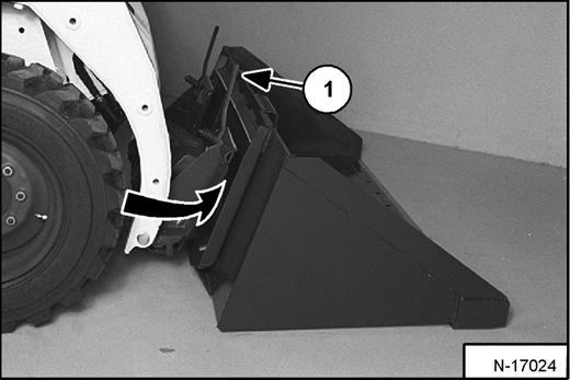
Pull the Bob-Tach levers all the way up (Item 1) [Figure OI-52]
Enter the loader and perform the PRE-STARTING PROCEDURE. (See PRE-STARTING PROCEDURE on Page OI-19.)
Lower the lift arms and tilt the Bob-Tach forward.
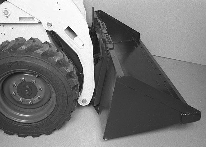
Drive the loader forward until the top edge of the BobTach is completely under the top flange of the bucket [Figure OI-52] (or other attachment). Be sure the BobTach levers do not hit the bucket.

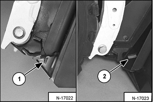
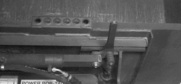
Push down on the Bob-Tach levers until they are fully engaged in the locked position (Item 1) [Figure OI-54] (wedges fully extended).
ATTACHMENTS AND BUCKETS (CONT’D)
Bob-Tach (Cont’d)
Figure OI-55
Warning
Before you leave the operator’s seat:
•Lower the lift arms, put the attachment flat on the ground.
•Stop the engine.
•Engage the parking brake.
•Raise seat bar
•(Foot Pedal Controls Only) Move pedals until both lock.
•(Advanced Control System (ACS) and Advanced Hand Controls (AHC) Move the hydraulic controls to the NEUTRAL POSITION to make sure that both lift and tilt functions are deactivated. The seat bar system must deactivate the lift and tilt control functions when the seat bar is up. Service the system if hand controls do not deactivate.
W-2398-1003
The wedges (Item 1) [Figure OI-55] must extend through the holes (Item 2) [Figure OI-55] in the mounting frame of the bucket (or attachment), securely fastening the bucket to the Bob-Tach.
Warning
Bob-Tach wedges must extend through the holes in attachment. Lever(s) must be fully down and locked. Failure to secure wedges can allow attachment to come off and cause injury or death.
W-2102-0497
Removing The Bucket Or Attachment
Lower the lift arms and put the attachment flat on the ground and lower or close the hydraulic equipment.
•If the attachment is hydraulically controlled (combination bucket, backhoe, etc.), stop the engine and relieve hydraulic pressure in the auxiliary circuit. (See Releasing Hydraulic Pressure (Loader and Attachment) on Page OI-13.) Disconnect the auxiliary hydraulic hoses from the loader.
Raise the seat bar, unfasten the seat belt, set the parking brake and exit the loader.
Enter the loader.
Perform the PRE-STARTING PROCEDURE. (See PRESTARTING PROCEDURE on Page OI-19.)
Start the engine.
Release the parking brake.
Press the PRESS TO OPERATE LOADER Button.
Be sure the lift arms are all the way down. Tilt the BobTach forward.
ATTACHMENTS AND BUCKETS (CONT’D)
Bob-Tach (Cont’d)
Warning
Bob-Tach levers have spring tension. Hold lever tightly and release slowly. Failure to obey warning can cause injury.

Installing The Bucket Or Attachment
The Bob-Tach is used for fast changing of buckets and attachments. See the appropriate Attachment Operation & Maintenance Manual to install other attachments.
Perform the PRE-STARTING PROCEDURE. (See PRESTARTING PROCEDURE on Page OI-19.)
Lower the lift arms and tilt the Bob-Tach forward.

Push and hold BOB-TACH "WEDGES UP" switch (Front Accessory Panel) (Item 1) [Figure OI-58] until levers are in unlocked position (Item 2) [Figure OI-58] (wedges fully raised).
ATTACHMENTS AND BUCKETS (CONT’D)
Power Bob-Tach (Cont’d)
Figure OI-59
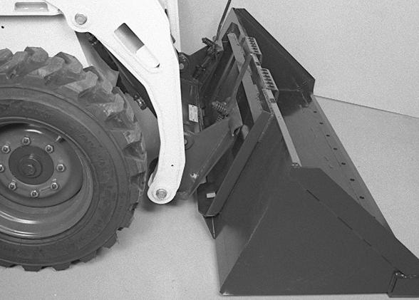
Drive the loader forward until the top edge of the BobTach is completely under the top flange of the bucket [Figure OI-59] (or other attachment).
Tilt the Bob-Tach backward until the cutting edge of the bucket (or other attachment) is slightly off the ground [Figure OI-60]
Push and hold BOB-TACH "WEDGES DOWN" switch (Front Accessory Panel) [Figure OI-58] until levers are fully engaged in the locked position (Item 2) [Figure OI58] (wedges fully extended).
The wedges (Item 3) [Figure OI-58] must extend through the holes in the mounting frame of the bucket (or attachment), securely fastening the bucket to the BobTach.
Bob-Tach wedges must extend through the holes in attachment. Lever(s) must be fully down and locked. Failure to secure wedges can allow attachment to come off and cause injury or death.
W-2102-0497
NOTE: The Power Bob-Tach system has continuous pressurized hydraulic oil to keep the wedges in the engaged position and prevent attachment disengagement. Because the wedges can slowly lower, the operator may need to reactivate the switch (WEDGES UP) before installing an attachment to be sure both wedges are fully revised before installing the attachment.
ATTACHMENTS AND BUCKETS (CONT’D)
Power Bob-Tach
Removing The Bucket Or Attachment
Lower the lift arms and put the attachment flat on the ground and lower or close the hydraulic equipment.
•If the attachment is hydraulically controlled (combination bucket, backhoe, etc.):
Stop the engine and relieve hydraulic pressure in the auxiliary circuit. (See Releasing Hydraulic Pressure (Loader and Attachment) on Page OI-13.)
Exit the loader and disconnect the hydraulic hoses from the attachment.)
Enter the loader.
Perform the PRE-STARTING PROCEDURE. (See PRE-STARTING PROCEDURE on Page OI-19.)
Start the engine.
Release the parking brake.
NOTE: The Power Bob-Tach system has continuous pressurized hydraulic oil to keep the wedges in the engaged position and prevent attachment disengagement. Because the wedges can slowly lower, the operator may need to reactivate the switch (WEDGES UP) before installing an attachment to be sure both wedges are fully revised before installing the attachment.
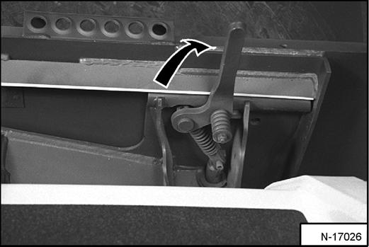
Push and hold the BOB-TACH "WEDGES UP" Switch (Front Accessory Panel) (Item 1) [Figure OI-61] until the wedges are fully raised.
Tilt the Bob-Tach forward.
Operating Procedure
When operating on a public road or highway, always follow local regulations. For example: Slow Moving Vehicle Sign or direction signals may be required.
Always warm the engine and hydrostatic system before operating the loader.
Important
Machines warmed up with moderate engine speed and light load have longer life.
Operate the loader with the engine at full speed for maximum horsepower. Move the steering levers only a small amount to operate the loader slowly.
New operators must operate the loader in an open area without bystanders. Operate the controls until the loader can be handled at an efficient and safe rate for all conditions of the work area.
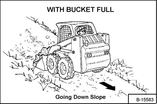
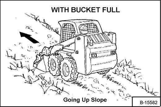
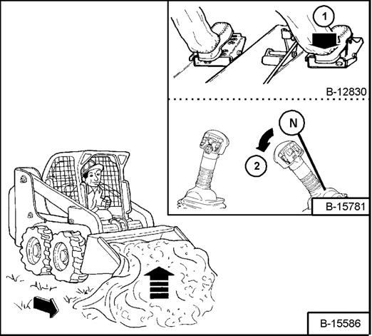
With a full bucket, go up or down the slope with the heavy end toward the top of the slope [Figure OI-63] & [Figure OI-64].
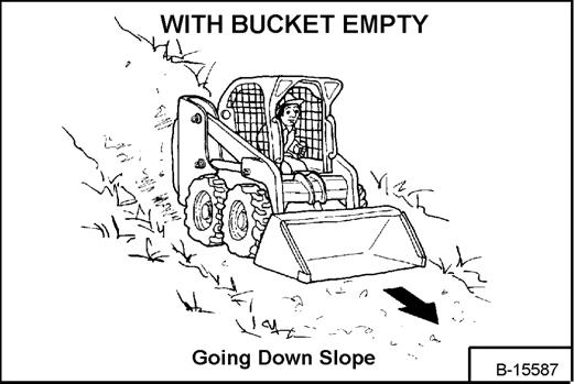
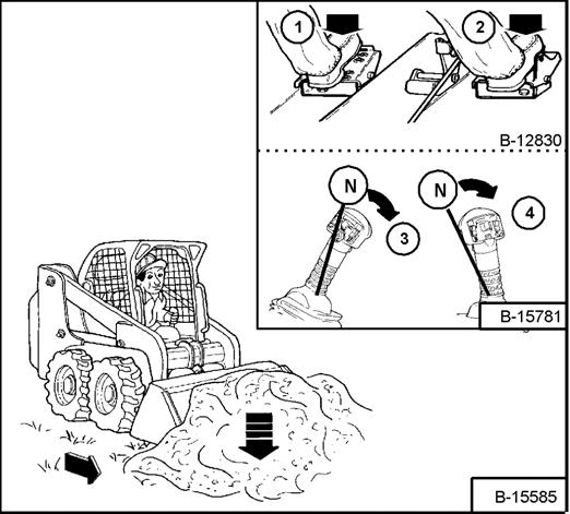
With empty bucket, go down or up the slope with the heavy end toward the top of the slope [Figure OI-65] & [Figure OI-66]
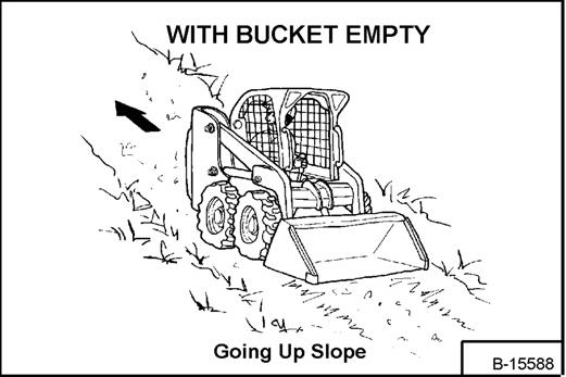
Warning
AVOID INJURY OR DEATH
•Keep the lift arms as low as possible.
•Do not travel or turn with the lift arms up.
•Turn on level ground.
•Go up and down slopes, not across them.
•Keep the heavy end of the machine uphill.
•Do not overload the machine.
Failure to obey warnings can cause the machine to tip or roll over and cause injury or death.
W-2018-1187
Raise the bucket only high enough to avoid obstructions on rough ground.
OPERATING PROCEDURE (CONT’D)
Filling the Bucket (Foot Pedals)
Figure OI-67
Warning
Load, unload and turn on flat level ground. Do not exceed Rated Operating Capacity (ROC) shown on sign (decal) in cab. Failure to obey warnings can cause the machine to tip or roll over and cause injury or death.
W-2056-0903
Filling the Bucket (Hand Controls)
Move the left hand lever, from neutral position (N), toward the operator (Item 3) [Figure OI-67] until the lift arms are all the way down.
Move the right hand lever, from neutral position (N) away from the operator (Item 4) [Figure OI-67] to put the cutting edge of the bucket on the ground.
Drive slowly forward into the material. Move the right hand lever, from neutral position (N), toward the operator (Item 2) [Figure OI-68] to raise the front of the bucket.
Push the top of the lift pedal (Item 1) [Figure OI-67] until the lift arms are all the way down.
Push the top of the tilt pedal (Item 2) [Figure OI-67] to put the cutting edge of the bucket on the ground.
Figure OI-68
Drive slowly forward into the material. Push the bottom of the tilt pedal (Item 1) [Figure OI-68] to raise the front of the bucket.
Drive backward away from the material.
Drive backward away from the material.
OPERATING PROCEDURE (CONT’D)
Emptying the Bucket (Foot Pedals)
Figure OI-69
Push the bottom of the lift pedal (Item 1) [Figure OI-69] to raise the lift arms. Push the top of the tilt pedal while raising the lift arms to level the bucket or attachment and help prevent material from falling off the back of the bucket or attachment.
Drive forward slowly until the bucket is over the top of the truck box or bin.
Push the top of the tilt pedal (Item 2) [Figure OI-69] until the bucket is empty. If all the material is near the side of the truck or bin, push it to the other side with the bucket.
Emptying the Bucket (Hand Controls)
Move the left hand lever, from neutral position (N), away from the operator to raise the lift arms [Figure OI-69] Move the right hand lever, from neutral position (N), away from the operator to level the bucket or attachment and help prevent material from falling off the back of the bucket or attachment.
Drive forward slowly until the bucket is over the top of the truck box or bin.
Move the right hand lever, from neutral position (N), away from the operator until the bucket is empty [Figure OI69]. If all the material is near the side of the truck or bin, push it to the other side with the bucket.
Warning
Never dump over an obstruction, such as a post, that can enter the operator cab. The machine could tip forward and cause injury or death.
W-2057-0694
Leveling the Ground (Using Lift Arms in Float Position) (Foot Pedals)
Figure OI-70
Push the top of the lift pedal (Item 1) [Figure OI-70] all the way forward until the pedal is in the locked position to put the lift arms in the float position.
Push the tilt pedal (Item 2) [Figure OI-70] to change the position of the cutting edge on the bucket.
With the bucket tilted farther forward, there is more force on the cutting edge and more loose material can be moved.
Drive backward to level loose material.
Push the bottom of the lift pedal to unlock from the float position.
Leveling the Ground (Using Lift Arms in Float Position) (Hand Controls)
Move the left hand lever, from neutral position (N), all the way down and in until the hand lever is in the locked position to put the lift arms in the float position [Figure OI-70]
Later ACS & AHC Models With Float Button
- To Engage: Press and hold the Float Button (Item 6) [Figure OI-70] while the lever is in neutral. Move the lever to the lift arm down position (Item 5) [Figure OI-70], then release the button.
- To Disengage: Press Float Button again or move the lever to the lift arm up position (Item 4) [Figure OI-70]
Move the right hand lever, from neutral position (N), to change the position of the cutting edge on the bucket [Figure OI-70].
With the bucket tilted farther forward, there is more force on the cutting edge and more loose material can be moved.
Drive backward to level loose material.
Move the left hand lever upward to unlock from the float position.
OPERATING PROCEDURE (CONT’D)
Digging Into the Ground (Foot Pedals)
Figure OI-71
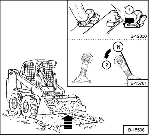
Put the lift arms all the way down. Push the top of the tilt pedal (Item 1) [Figure OI-71] until the cutting edge of the bucket is on the ground.

Drive forward slowly and continue to tilt the bucket down (Item 1) [Figure OI-71] until it enters the ground.
Push the bottom of the tilt pedal a small amount to increase traction and keep an even digging depth. Continue to drive forward until the bucket is full. When the ground is hard, raise and lower the cutting edge of the bucket with the tilt pedal while driving forward slowly.
Push the bottom of the tilt pedal (Item 1) [Figure OI-72] to tilt the bucket backward as far as it will go when the bucket is full.
Digging Into the Ground (Hand Controls)
Put the lift arms all the way down. Move the right hand lever away from the operator (Item 2) [Figure OI-71] until the cutting edge of the bucket is on the ground. Drive forward slowly and continue to tilt the bucket down until it enters the ground.
Move the right hand lever toward the operator a small amount to increase traction and keep an even digging depth. Continue to drive forward until the bucket is full. When the ground is hard, raise and lower the cutting edge of the bucket with the hand lever while driving forward slowly.
Move the right hand lever toward the operator (Item 2) [Figure OI-72] to tilt the bucket backwards as far as it will go when the bucket is full.
OPERATING PROCEDURE (CONT’D)
Backfilling (Foot Pedals)
Figure OI-73
Lower the lift arms (Item 1) [Figure OI-73] and put the cutting edge of the bucket on the ground. Drive forward to the edge of the hole to push the material into the hole.
Tilt the bucket forward (Item 2) [Figure OI-73] as soon as it is past the edge of the hole.
If necessary, raise the lift arms to empty the bucket.
Backfilling (Hand Controls)
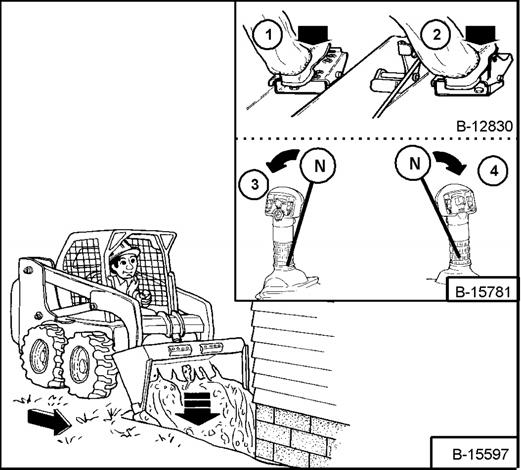
Lower the lift arms (Item 3) [Figure OI-73] and put the cutting edge of the bucket on the ground. Drive forward to the edge of the hole to push the material into the hole.
Tilt the bucket forward (Item 4) [Figure OI-73] as soon as it is past the edge of the hole.
If necessary, raise the lift arms to empty the bucket.
Parking The Bobcat Loader
Stop the Bobcat Loader on level ground.
Figure OI-74
Warning
Before you leave the operator’s seat:
•Lower the lift arms, put the attachment flat on the ground.
•Stop the engine.
•Engage the parking brake.
•Raise seat bar
•(Foot Pedal Controls Only) Move pedals until both lock.
•(Advanced Control System (ACS) and Advanced Hand Controls (AHC) Move the hydraulic controls to the NEUTRAL POSITION to make sure that both lift and tilt functions are deactivated. The seat bar system must deactivate the lift and tilt control functions when the seat bar is up. Service the system if hand controls do not deactivate.
W-2398-1003
Engage the parking brake.
Lower the lift arms fully and put the attachment flat on the ground [Figure OI-74].
Pull the engine speed control lever all the way backward. Turn the key switch to STOP (Standard Panel) OR press the STOP Button (Deluxe Panel).
Lift the seat bar and make sure the lift and tilt functions are deactivated.
Unbuckle the seat belt.
Remove the key from the switch (Standard Panel) to prevent operation of the loader by unauthorized personnel.