23 minute read
TROUBLESHOOTING Chart


The following troubleshooting chart is provided for assistance in locatingand correcting problems which are most common. Many of the recommended procedures must be done by authorized Bobcat Service Personnel only.
Problem Cause
Engine will not turn over with the starter.
Engine will not start or is difficult to start.
Engine misses, runs irregularly or stops.
Engine overheats.
Key To Correct The Cause
1.Battery has lost its charge.
2.Loose battery connections.
3.Loose starter connections.
4.Damaged starter switch.
5.Broken or damaged wire harness.
6.Damaged starter or solenoid.
7.Fuse has damage.
8.Wrong starting procedure.
9.No fuel in tank.
10.Air cleaner is dirty.
11.Fuel vent in cap has restricted.
12.Fuel line has air leak, dirt or water.
13.Hydraulic/Hydrostatic load on engine.
14.Fuel pump is damaged.
15.Ignition system is damaged or timing is wrong.
16.Incorrect crankcase oil.
17.Dirty fuel mixture.
18.Poor compression.
19.Water in the fuel line.
20.Engine is overloaded.
21.Radiator grill is dirty.
22.Dirty engine oil.
23.Restricted exhaust system.
24.Coolant level is low.
25.Oil cooler has restriction.
Checks And Adjustments
Oil Pressure
Engine oil pressure can be checked by installing a gauge in the sender switch port. Normal pressure is 35–40 PSI at 2000 RPM.
Valve Clearance
Make adjustment of valve clearance with the engine stopped
Put a feeler gauge between rocker arm and pushrod and turn adjustment screw in or out to get the correct clearance [A]. (See Section 8B SPECIFICATIONS for the correct clearance.)
Compression
Make sure the crankcase oil level is correct, and the battery has a full charge.
Start the engine and operate for about 30 minutes at 1200 RPM or until the engine is at normal operating temperature.
Stop the engine and remove all the spark plugs.
Put the carburetor throttle plate and choke plate in the full open position.
Install a compression gauge in the No. 1 cylinder. (No. 1 cylinder is at the rear of the machine.)
Operate the starter until it turns the engine at least five compression strokes and record the highest reading. Count the number of compression strokes to get the highest reading.
Test each cylinder.
Make a comparison of the highest and the lowest compression readings. If the lowest is at least 75% of the highest compression pressure are normal [B]
If one or more of the cylinders show a low reading, put 1/2 oz. (14,75 ml) of oil in the low reading cylinders and make the compression test again.
If there is a lot of increase in the compression, the piston rings are worn.
CHECKS AND ADJUSTMENTS (Cont’d)
Compression (Cont’d)
If compression does not show increase, the valves are not operating correctly.
If two cylinders side by side each havea low compression and putting oil in the cylinders does not cause an increase in compression, the damage could be a cylinder head gasket leak between the cylinders.
Head gasket leakage can cause oil or coolant to enter the cylinders and cause damage to the engine.
Carburetor, Throttle And Governor Adjustments
Put blocks under the frame of the bobcat so that there is no danger of the machine falling and causing personal injury.
Remove the belt shield [A]
Loosen the governor fastening bolts and make adjustment of belt to give 1/4 inch (6,35 mm) freeplay[B] Tighten the governor fastening bolts.
Install the belt shield.
NOTE:If only the belt needs adjustment, make adjustment to the linkage (Item 1) [C].
Disconnect the throttle rod and the governor linkage (Item 1) [C].
Remove the linkage from the governor control arms (Item 2) [C]
CHECKS AND ADJUSTMENTS (Cont’d)
Carburetor, Throttle And Governor Adjustments (Cont’d)
Make adjustment of the linkage so the distance between the pivot points are 4–7/8 inches (123,8 mm) [A].
Check that there is free movement of the throttle plate in the carburetor.
Install the linkage on the governor control arm.
Loosen the control arm stop until it has no effect on the governor control arm [B]
Loosen the two screws on the governor control arm [C]
Move the governor control arm and control arm of the carburetor linkage as shown in [C]
Hold the control arm and linkage in position and tighten the two screws.
Start the engine and turn theidle adjustment screw on the carburetor to adjust the idle speed at 550–650 RPM [D]
Adjust the ignition timing. (See Page 7B–5Ignition Timing for the correct procedure.)
Put the throttle lever in idle position.
Hold the governor control arm all the way to the left as shown in [C]. then adjust the throttle rod until the pin goes into the hole in the throttle linkage.
Start the engine and put the throttle lever (inside the Operator Cab) at full RPM. Make adjustment to the top bolt until the engine runs at 2600–2675 RPM.
Turn the control arm stop until there is an increase of 25 RPM [B].
CHECKS AND ADJUSTMENTS (Cont’d)
Governor Oil Level
See the SERVICE SCHEDULE Section 1 for the service interval for checking the governor oil level. Use the following procedure:
Remove the check plug (Item 1) [A].
If oil flows out the hole, the level is adequate.
If no oil flows out the hole, remove the fill plug (Item 2)[A] at the top of the governor and add SAE 10W–30 or 10W–40 until oil flows from the check plug hole. Install the plug and tighten.
Grease the fittings at the shaft every 200–500 hours with a multi–purpose grease.
Ignition System
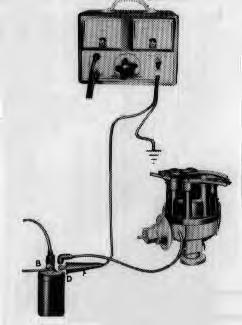
Coil to Ground Voltmeter Test
Connect the voltmeter wires as shown in [B].
Operate the starter until the breaker points are fully closed.
Turn all the lights and accessories off.
Turn the ignition switch on.
If the voltmeter reading is 0.25 volt or less the primary circuit from the oil to the ground is good.
If the voltmeter reading is more than 0.25 volt test the voltage loss between each of the following:
The connector marked DIST on the coil and the connection on the distributor.
The moving breaker point and the stationary breaker point.
The breaker point the distributor. The distributor housing the engine ground.
If the voltage loss of all the above has a total of more than 0.25 volts, it will cause bad engine performance.
Spark Plug Wires Resistance Test
These wires include the wires connecting the distributor cap to the spark plug and the wire connecting the center connection of the distributor cap to the center connection of the ignition coil.
these wires are the radio resistance–type. The resistance of each wire must not be more than 5000 ohms per inch. When checking the resistance of the wires or adjusting ignition timing, do not damage the wires. This can cause separation in the conductor.
Spark Plug Test
Check and clean the electrodes and adjust the spark plug gap. After the gap is correct, check the plugs on a testing machine. Compare the operation of the old plug with a new plug.
CHECKS AND ADJUSTMENTS (Cont’d)
Distributor Tests
Test Connections
Disconnect the distributor primary wire from the coil. Connect a short jumper wire to the DIST connection of the coil and the distributor primary wire. Connect the read wire to the jumper wire.
Connect the black wire to a good ground location on the engine
Dwell Angle Check
Connect the tester. Turn the test control knob to the set position.
Adjust the control knob until the needle on the dwell meter is in alignment with the set line.
Start the engine and let it idle. Turn the cylinder selector to the four.
Read the swell angle on the dwell meter and compare the reading to specifications. (See Section 8 TECHNICAL DATA.)
Turn off the engine. If the dwell angle was below the specified amount, the breaker point gap is wide. If the dwell angle was above the specified amount, the breaker point gap is narrow.
If the dwell is at specifications, turn the test selector knob to the OFF position and disconnect the tester leads and jumper wire.
Make adjustment to the points as needed.
Spark Strength Tests
Remove the coil high voltage wire fromthe distributor cap. Turn the ignition switch to ON position.
While holding the high tension lead about 3/16 inch from the cylinder head or any other good ground turn the engine over. If the spark is good, the problem is in the secondary circuit. Spark plugs or spark plug wires are damaged.
If there is no spark or a small amount of spark, the problem is in the primary circuit. The coilto the distributor wire, or the coil is damaged.
Ignition System Tests
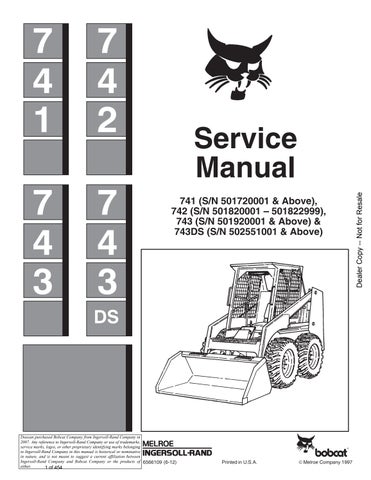
Battery To Coil Voltmeter Test
Connect the voltmeter wires as shown in [A]. Connect a jumper wire to the distributor connection of the coil andto a good ground location on the distributor housing.
Turn the lights and accessories off. Turn the ignition switch to ON position.
If the voltmeter reading is between 4.5 and 6.9 bolts the primary circuit from the battery to the coil is good.
CHECKS AND ADJUSTMENTS (Cont’d)
Ignition System Tests (Cont’d)
Battery To Coil Voltmeter Test (Cont’d)
If the voltmeter reading is more than 6.9 volts, check the following:
The battery and cables for loose connections or corrosion.
The primary insulation, broken wires and loose or corroded connections.
If the voltmeter reading is less than 4.5 volts, the ignition resistor must be replaced.
Check the start relay to the ignition switch for damage.
Starting Ignition Circuit Voltmeter Test
Connect the voltmeter wires. (See Page 7B–3.)
Disconnect and ground the coil to distributor high voltage wire at the distributor.
With the ignition switch in the OFF position turn the engine with an auxiliary starter switch while reading the voltage loss.
If the voltage loss is 0.4 volt or less, the starting ignition circuit is good.
If the voltage loss is more than 0.4 volts clean and tighten the connections in the circuit or make replacement of the wiring as needed.
Breaker Point Gap Adjustment
Turn the engine over until the points are fully opened. Put the correct thickness blade of a clean feeler gauge between the breaker points [A] & [B]. Make adjustment of the points to correct gap and tighten the screws.
Clean the cam area, then put a small amount of cam lubricant on the cam when new points are installed. Do not use engine oil as a lubricant.
Ignition Timing
When installing distributor (Brown Cap) do the following: Align the timing marks as shown [D]
Install the distributor and rotor marks (Item 1) [C] and housing marks (Item 2) [C] in alignment.
Timing Marks Location
The timing mark locations are shown in [D].
CHECKS AND ADJUSTMENTS (Cont’d)
Initial Ignition Timing
Disconnect the vacuum advance hose from the distributor and put a plug in the hose.
Clean and mark the correct timing mark with chalk or white paint.
Connect a timing light to No. 1 cylinder spark plug wire [A]. Connect a tachometer to the engine.
Start the engine and decrease the idle speed to 750 RPM to make sure that the centrifugal advance is not operating. Make the adjustment of the initial ignition timing to 12 ° BTDC by loosening the 7/16 inch bolt and rotating the distributor in the correct direction.
Check the centrifugal advance for correct operation by starting the engine and running the engine at 2000 RPM. If the ignition timing advances, the centrifugal advance mechanism is operating correctly. Note the engine speed when the advance starts and the amount of totaladvance. Stop the engine. Connect the vacuum hose.
Carburetor Repair
Repair the four screws (Item 1) [B].
Remove the throttle body (Item 2) [B] and the gasket (Item 3) [B] from the fuel body (Item 4)[B]. Be careful not to cause damage to the float assembly (Item 5) [B]
Put a screwdriver against the float axle (Item 6)[B] at the slotted side of the float hinge and push the axle through the slotted side of the bracket. Remove the hinge and remove the float assembly (Item 5) [B]
Remove the fuel valve needle (Item 7)[B], the valve seat (Item 8) [B] and the fiber washer (Item 9) [B]
Use new parts in the repair kit to replace the above parts.
The correct float lever for the carburetor is 1–1/8 inch to 1–3/16 inch as measured from the machined surface of the throttle body (inverted) to the top of the float [C] Measurement is made without the gasket.
Use a needle nose pliers to bend the lever on the float body to get the correct float adjustment.
NOTE:If parts need replacement and are not in the carburetor kit, replace the carburetor assembly.
FIRING ORDER –1–2–4–3
Engine Diagnosis And Testing
Check the lift of each camshaft lobe and make a note of the readings.
Remove the rocker arm cover.
Remove the rocker arm shaft assembly.
ENGINE DIAGNOSIS AND TESTING (Cont’d)
Camshaft Lobe Lift (Cont’d)
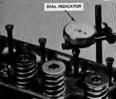
Make sure the pushrod is in the valve lifter socket.Install a dial indicator so the ball socket adapter of the indicator is on the end of the pushrod and is vertical with the pushrod movement [A]
Turn the crankshaft over until the lifter is in its lowest position, highest indicator reading.
Position the dial indicator at zero. Continue to rotate the crankshaft at a slow rate until the pushrod is in the highest position, highest indicator reading.
Compare the total reading on the indicator with the specifications.
To check the original indicator reading, continue to rotate the crankshaft until the indicator reads zero. If the reading on any lobe is below the specified wear limits, the camshaft and the valve lifters must be replaced.
Remove the dial indicator gauge. Install the rocker shaft assembly. Install the rocker cover.
Crankshaft End Play
Move the crankshaft toward the rear, flywheel end, of the engine.
Install a dial indicator and position the contact point against the crankshaft flange at the front of the engine and the indicator is parallel to the crankshaft [B].
Position the dial indicator at zero. Push the crankshaft forward and note the reading on the dial.
If the end play is more than the wear limit, according to specifications, install new thrust washers. If the end play is less than the minimum limit, check the thrust bearing surfaces for scratches, rough areas or debris.
Flywheel Surface Alignment Check
Move the crankshaft fully forward or to the rear. Install a dial indicator so that the indicator point is against the flywheel surface.
Position the dial indicator at zero and turn the crankshaft. Check the indicator reading.
If alignment is not specification, remove the flywheeland check for dirt or other debris between the flywheel and crankshaft flange. If alignment is not to specifications, install a new flywheel or grind the crankshaft or flywheel as needed to correct the alignment.
ENGINE DIAGNOSIS AND TESTING (Cont’d)
Camshaft End Play
Push the camshaft toward the rear, flywheel end, of the engine.
Install a dial indicator. Position the indicator point on the hub of the camshaft sprocket.
Position the dial indicator at zero.
Put a large screwdriver between the camshaft sprocket and the cylinder head. Pull the camshaft forward and release it.
Check the indicator reading. If reading is more than the specification replace the thrust plate that holds the camshaft.
Engine Removal
Remove the temperature sender [A].
Install a fitting of the correct threads in the sender hole location [B]
Install a hose on the fitting and drain the coolant into a container [C]
Remove the grill [D].
ENGINE REMOVAL (Cont’d)
Remove the radiator cap [A].
Remove the line from the coolant recovery tank and remove the tank [B]
Loosen the exhaust pipe clamp [C]
ENGINE REMOVAL (Cont’d)
Remove the bolts from the manifold [A].
Remove the exhaust pipe from the muffler [B]
Remove the throttle rod from the governor linkage [C]
Remove the coil wire and removethe other wires from the coil [D].
ENGINE REMOVAL (Cont’d)
Remove air cleaner hose from the engine [A]
Remove the coolant hoses from the engine.
Remove the solenoid from the recovery tank bracket[B]
Disconnect the fuel line from the engine.
Remove the engine ground cable [C]
Remove the engine mounting bolts [D].
Raise the operator guard.
ENGINE REMOVAL (Cont’d)
Disconnect the engine harness from the chassis harness [A]
Remove the choke control from the front panel and put it in the engine compartment [B]
Remove any other items necessary.
Remove the engine using a table as shown in [C]
ENGINE REPAIR
Cylinder Head
Do not grind more than .010 inch (0,154 mm) from the cylinder head gasket surface. Remove all rough edges and scratches with an oil stone.
Valve Guides
If the valve guides become worn, it will be necessary to install valves with an oversize stem.
Valves with oversize stems are available in the following oversize amounts:
.003 inch.015 inch.030 inch
Use a reamer of the correct size to make valve guides larger.
When going from a standard size valve to an oversize valve, always use the reamer in steps. Grind the valve seat after the valve guide.
Grinding The Valve Seats
The valve seats are part of the cylinder head.If the valve seats become damaged so that the valves and seat are not in correct contact, grinding of the valve seats is necessary [D].
Grind both the intake and the exhaust valve seats at 45° . Grind only enough to give the valve seat a smooth surface.
Grind the valve seat the correct width. (See SPECIFICATIONS Section 8B.) Use a 60 ° grinding wheel to remove the material from the bottom of the valve seat and a 30° grinding wheel for the top of the valve seat. The valve seat must be in contact at approximately the center of the valve surface.
TO REMOVE STOCK FROM TOP OF SEAT, USE 30° WHEEL 45°
TO REMOVE STOCK FROM BOTTOM OF SEAT, USE 60° WHEEL
VALVE SEAT WIDTH
ENGINE REPAIR (Cont’d)
Valves
Small burns, grooves, etc., can be removed. Remove valves that are damaged, if the surface alignment cannot be corrected by finishing or if the valve stem clearance is more than specifications allow.
Grinding Valves
If the valve surface alignment is not within specifications grind the valve to a 45 ° angle. Remove only enough material to correct the alignment or to make thesurfaces smooth. If the edge of the valve headis less than 1/32 inch thick after grinding [A], install new valve as the old valve will cause engine to run hot. Remove all grooves or scratches from the end of the valve stem, and make chamfer as needed. DO NOT remove more than 0.010 inch (0,245 mm) from the end of the valve stem.
If the valve or valve seat has been finished, it will be necessary to check the clearance between the rocker arm and the valve stem with the rocker assembly installed in the engine.
Selecting Fitting Of The Valves
If the valve stem to valve guide clearance is more than the wear limit, use a reamer to cut the valve guide to the next oversize valve stem. Valves with oversize stem diameters of 0.003 inch, 0.015 inch and 0.030 inch are available as service parts. Grind the valve seat after the valve guide has been cut.
Camshaft Repair
Remove small marks from the camshaft machined surfaces with a smooth oil stone.
Crankshaft
Remove small marks with an oil stone. If the journals are damaged or worn, they must be machined to the correct size for the next size smaller bearing.
Repairing Journals
After machining the bearing surfaces, put a chamfer inthe oil holes; then finish the bearing surfaces with a No. 320 grit cloth and engine oil. Crocus cloth may also be used for finishing.
To Check Crankshaft Or Connection Rod Bearings With Plastigage
Clean crankshaft bearing surfaces. Check the surfaces and thrust bearings for damage. When making replacement of standard size bearings, install bearing of minimum specified clearance. If the needed clearance cannot be made with a standard bearing use a 0.002 inch size smaller in combination with a standard bearing to get the correct clearance. (See SPECIFICATIONS Section 8B–1.)
ENGINE REPAIR (Cont’d)
To Check Crankshaft Or Connection Rod Bearings
With Plastigage (Cont’d)
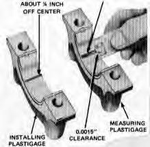
Put a piece of plastigage on the bearing surface across the full width of the bearing cap and about 1/4 inch (6,35 mm) off center [A]
Install the cap and tighten the bolts to correct torque. DO NOT turn the crankshaft while Plastigage is in position. Remove the cap. Using the Plastigage scale, check the width of plastigage at the widest point to get the minimum clearance. The difference between the readings is the taper of the bearing surfaces.
If the clearance is more than specified limits, on the connecting rod bearings, use a 0.002 inch size smaller bearing in combination with the standard bearings. Bearing clearance must be within specified limits. If0.002 inch size smaller main bearings are used on more than one bearing surface, be sure they are installed in the cylinder block side of the bearing. If standard size and 0.002 inch smaller size bearings do not make clearance within the needed limits, machine the crankshaft bearing surface, and install the smaller size bearings.
After the bearing has been checked, remove Plastigage and put a small amount of oil on the bearing surface and the bearings. Install the bearing cap. Tighten the bearing caps bolts to the correct torque.
Do the above for all bearings that need replacement.
Install Pistons
Pistons are available for service in standard sizes and over sizes.
The standard size pistons are color coded red or blue or have .0025 O.S. marked on the top. Refer to SPECIFICATIONS Section 8B–1 for standard size piston dimensions.
Measure the piston diameter to be sure you have the specified clearance. When a new piston has been checked for clearance, mark the piston to the cylinder to which it was checked in. If the taper and piston to cylinder bore clearance conditions of the cylinder bore are within specified limits, new piston rings will give good service. If new rings are to be installed in a used cylinder that has not been finished, remove the cylinder wall glaze with a hone. Be sure to clean the cylinder bore after honing.
Find the correct size piston to be used by marking a cylinder bore check.
Find the correct size piston to give the correct clearance. (Refer to SPECIFICATIONS section 8B–1.) Measure the piston 2–1/4 inches (57,15 mm) below the top and a 90° to the piston pin bore.
Make sure the piston and cylinder block are at room temperature, 70°F (21,1°C). After any finishing option, let the cylinder bore cool and be sure the piston and the bore are clean and dry before the piston fit is checked.
ENGINE REPAIR (Cont’d)
Installing Piston Rings
The piston uses two compression rings and one oilcontrol ring. the lower compression ring is stepped on the bottom outer edge and the upper ring is chrome plated and tapered on the outside diameter. Both rings are marked top and must be installed correctly. The upper ring, when new, has a red and brown compound on the outer edge. This compound must not be removed. The oil control rings have narrow ring cases and can be installed either way.
Use the correct size ring for the size of cylinder bore you have.
Put the ring in the cylinder bore it is going to be used in.
Use the head of a piston to push the ring in the bore about 1 inch (25,4 mm) so that the ring is square with the cylinder wall. Be careful not to damage the ring or the cylinder bore.
Measure the gap between the ends of the ringwith a feel gauge [A]. If the ring gap is not in the specified limits,use another ring set.
Check the side clearance of the compression rings with a feeler gauge installed between the ring and its lower edge [B]. The gauge must move easily around the ring circumference. If the grooves are worn, make replacement of the piston.
Installing The Piston Pins
Pistons and piston pins are available as a unit only and cannot be purchased as individual parts. Keep the correct pins and pistons together.
Valve Rocker Arm And Shaft Assembly
Use a hone to remove small surface damage to the rocker arm shaft and to the rocker arm bore.
If the valve end of the rocker arm has a grooved radius replace the rocker arm. You cannot grind this surface.
Push Rods
Make sure the push rods are straight.
If the push rod is not in specification replace the push rod.
Cylinder Block
Finishing The Cylinder Walls
Before any cylinder is machined all main bearing caps must be positioned and tightened to the correct torque. Finish only the cylinder or cylinders that need to be finished. All pistons are the same weight, both standard and oversize; and various sizes of pistons can be used without changing the engine balance. Finish the cylinder with the most wear first to find the maximum oversize.
CYLINDER BLOCK (Cont’d)
Finishing The Cylinder Walls (Cont’d)
Finish the cylinder to within 0.0015 inch (.038 mm) of the oversize diameter. This will leave enough material for the final step of honing for correct surface finish and pattern. Use a motor driven hone with spring pressure. Use an RPM of 300–500 and grit sizes 180–200. Use a lubricate mixture of equal parts of kerosene and SAE No. 20 motor oil
Cylinder Heads
Cleaning The Cylinder Heads
With the valves installed to protect the valve seats, remove deposits from the combustion chambers and valve heads with a scraper and a wire brush. Be careful not to damage the cylinder head gasket surface. Remove the valves and clean the valve guide cleaning tool. Use cleaning solvent to remove grease and other debris. Clean all the bolt holes. Remove the valves and clean the valve guide cleaning tool. Use cleaning solvent to remove grease and otherdebris. Clean all the bolt holes. Remove all the deposits from the valves with a fine wire brush or buffing wheel.
Checking The Cylinder Heads
Check the cylinder head for cracks and check the gasket surface for debris and scratches.
When a cylinder head is removed because of gasket leaks, check the flatarea of the cylinder head gasket surface for correct specifications. If necessary to finish the cylinder head gasket surface, do not machine off more than 0.010 inch (0,254 mm).
Check the valve seat with a gauge. If the wear is more than specifications allow, grind the valve and valve seat. Measure the valve seat width. Grind the valve seat when the width is not in specification.
Check the valve surface and the edge of the valve head for damage. Check the stem for damage and the end of the valve stem for wear.
Check the valve stem to valve guide clearance of each valve in its correct valve guide.
Check the springs for the correct pressure at the specified spring lengths. Use tool (P/N 6513–DD). Replace any springs not in specifications.
Check each spring for being round, using a steel square and a flat surface. Put the spring and square on end on the flat surface. Move the spring up to the square. Turn the spring and check the space between the top coil of the spring and the square. The out of round limits are 0.078 inch (1,98 mm).
Follow the same procedure to check new valve springs before installation. Be sure the correct spring is installed. The springs are color coded.
Tappets
Cleaning The Tappets
Clean the tappets in cleaning solvent and wipe the tappets with a clean lint free cloth
Checking The Tappets
Check the tappets for wear or damage. Check the bottom end of the tappet to make sure that it has a small amount of convex. Replace tappets that are damaged, worn, or if the bottom is not smooth. If the bottom surface is worn flat, it can be used with the original camshaft only.
CAMSHAFT
Cleaning And Checking The Camshaft
Clean the camshaft in solvent and wipe it dry. Check the camshaft lobes for damage and war. The camshaft does not need replacement unless the lobe lift is worn more than 0.005 inch (0,127 mm).
The lift of the camshaft lobes can get check with the camshaft installed in the engine or on the centers. Make reference to Page 7B–10 Camshaft Lobe Lift.
CRANKSHAFT
Checking The Crankshaft
Measure the diameter of each journal in at least four locations to look for out of round taper or smaller size conditions.
Flywheel
Checking The Flywheel
Check the flywheel for cracks, or other damage.
Check the ring gear of r wear and damage to the teeth. If the teeth have damage, install a new ring gear. With the flywheel installed on the crankshaft, check the flywheel surface alignment.
Connecting Rods
Cleaning The Connecting Rods
Remove the bearings from the rod and cap. Mark the bearings for identification if you are to use them again. Clean the connecting rods in solvent, including the rod bore and under the bearings. Clean all passages with compressed airusing a low air pressure.
Checking The Connecting Rods
Check the connecting rod bearing bores for out of round and taper. Check the inside diameter of the connecting rod piston pin bore. If the pin bore in the connecting rod is larger than the specification, install a 0.002 inch oversize piston pin. First fit the oversize piston pin to the piston pin bore by using a reamer tool Then assemble the piston, the piston pin and the connecting rod.
PISTONS, PINS AND RINGS
Cleaning The Pistons, Pins And Rings
Remove debris from the piston surfaces. Clean debris from the piston skirt, piston pins and rings with solvent.
Clean the ring grooves with a ring groove cleaner. Make sure the oil ring slots are clean.
Checking The Pistons, Pins And Rings
Replace the pistons that show signs of over maximum wear or damage.
Check the piston to cylinder bore clearance by measuring the piston and bore diameters. Refer to Page 7B–19 Cylinder Block for the bore measurement procedure. Measure the outside diameter of the piston with micrometers about 2–14 inches (57,15 mm) below the dome and at 90° to the piston pin bore. Check the ring side clearance. (See Page 7B–14 Installing Piston Rings.)
Check the outside diameter of the piston pin and the inside diameter of the pin bore in the piston. Make replacement of any piston pin or piston that is not in specifications.
Replace all rings that have damage. Check the end gap and the side clearance. Rings must not be moved from one piston and installed on another.
Main Bearings And Connecting Rod Bearings
NOTE:Main bearings have color codes to identify size. See SPECIFICATIONS Section 8B–1.
Cleaning Bearings
Clean the bearing inserts and caps in solvent and dry them with compressed air. Do not remove deposits from the bearing shells.
Checking Bearings
Check each bearing carefully. Bearings that have damage or excessive wear need replacement. Check the clearance of bearings that look good with Plastigage. (See Page 7B–15 To Check Or Connection Rod Bearings With Plastigage.)
Cylinder Block
Cleaning The Cylinder Block
After any cylinder bore repair operation clean the bore with soap and water. The rinse the bore with clean water to remove the soap and wipe the bore with a clean cloth with engine oil on it.
If the engine is disassembled clean the block with solvent. Remove old gasket materialfrom all machined surfaces. Remove all pipe plugs that seal oil passages and clean all the passages. Clean all passages, bolt holes, etc., with compressed air. Make sure the threads in the cylinder head bolt holes are clean.
Use a tap to clean the threads and to remove any debris. Clean the groove in the crankshaft bearing and bearing retainers.
CYLINDER BLOCK (Cont’d) Checking The Cylinder
Check the cylinder walls for damage and wear. Check the cylinder bore for out of round and taper. Measure the diameter of each cylinder bore at the top, center and bottom with the gauge positioned at the right angles and parallel to the centerline of the engine. Use only the measurement at 90 ° to the engine centerline when calculating the piston to cylinder bore clearance.
Machine the cylinders that are damaged or when out of round or taper is more than the wear limits allow.
Oil Pump
Cleaning The Oil Pump
Wash all parts in a solvent and dry them with compressed air. Use a brush to clean the inside of the pump housing and the pressure relief valve chamber. Be sure all dirt and metal particles are removed.
Checking The Oil Pump
Check the inside of the pump housing and the outerrace and rotor for damage or wear.
Measure the outer race to housing clearance [A]. check the clearance between the outer race and the rotor lobes [B]
With the rotor assembly installed in the housing. Put a straight edge over the rotor assembly and the housing. Measure the clearance (rotor end play) between the straight edge and the rotor [C]. The outer race, shaft and rotor can be replaced only as an assembly. Check the drive shaft to housing bearing clearance by measuring the outside diameter of the shaft and the inside diameter of the housing bearing. Check the relief valve spring tension.
If the spring tension is not within specifications and the spring is worn or has damage, install a new spring. Check the relief valve piston for damage and free movement in the bore.