9 minute read
ELECTRICAL SYSTEM INFORMATION


Description
The loader has a 12 volt, negative ground electrical system. There are two main circuits.
1.The charging circuit has an alternator (with built–in regulator) and a battery.
2.The starting circuit has glow plugs, starter motor and solenoid for starting the engine.
Optional equipment for the loader are frontand rear lights, windshield wiper, horn and back–up alarm.
The electrical system is protected by two fuses installed in the instrument panel. Fuses protect the electrical system from an over–load.
Troubleshooting
Chart
Instructions are necessary before operating or servicing machine. Read Operation & Maintenance Manuals, Handbook and signs (decals) on machine. Follow warnings and instructions in the manuals when making repairs, adjustments or servicing. Check for correct function after adjustments, repairs or service. Failure to follow instructions can cause injury or death.
The following troubleshooting chart is provided for assistance in locating and correcting problems. Many of the recommended procedures must be done by authorized Bobcat Service Personnel only.
Problem
Battery will not take a charge. 1,
3, 4, 5 Alternator will not charge.
Starter will not turn the engine.
Key To Correct The Cause
1.Alternator belt is loose or damaged.
2.Battery connections are dirty or loose.
3.Battery is damaged.
4.The ground connection is not making a good contact.
5.The alternator is damaged.
6.The engine is locked.
7.The starter is damaged.
8.The wiring or the solenoid is damaged.
9.Check the fuses.
Checking The Battery
The tool listed will be needed to do the following procedure:
MEL10004 – Battery Tester
To make a safe and complete check of the battery, see the Battery Manual (P/N 6566047).
The Battery Manual has all the information needed for checking and servicing the battery. Replace the battery as needed.
Batteries contain acid which burns eyes and skin on contact. Wear goggles, protective clothing and rubber gloves to keep acid off body.
In case of acid contact, wash immediately with water. In case of eye contact get prompt medical attention and wash eye with clean, cool water for at least 15 minutes.
If electrolyte is taken internally drink large quantities of water or milk! DO NOT induce vomiting. Get prompt medical attention.
W–2065–1296
DO NOT remove the vent caps from the battery while charging the battery. The battery vent caps will decrease the possibility of battery being exploded by an external spark.
Removal And Installation
Disconnect the negative (–) cable first.
Disconnect the positive (+) cable [A].
Remove the battery holddown clamps (Item 1) [B], [C] & [D]
Remove the battery from the loader.
Alternator
Alternator Belt Adjustment (741)
Open the rear door.
Remove the belt shield bolts.
Remove the belt shield from the engine [A]
Loosen the adjustment bolt [B]
Move the alternator to set the belt tension at 5/16’’ (8 mm) deflection with 15 pounds of force [C]
Tighten the adjustment bolt [B]
Install the belt shield.
ALTERNATOR (Cont’d)
Alternator Belt Adjustment (742)
Open the rear door.
Remove the belt shield bolts.
Remove the belt shield from the engine [A]
Loosen the adjustment bolt (Item 1) [B].
Move the alternator to set the belt tension at 1/4’’ (6 mm) deflection with 20 lbs. (9 kg) pressure [B]
Tighten the adjustment bolt.
Install the belt shield.
ALTERNATOR (Cont’d)
Alternator Belt Adjustment (743)
Open the rear door.
Remove the belt shield bolts.
Remove the belt shield from the engine [A]
Loosen the adjustment bolt (Item 1) [B]
Move the alternator to set the belt tension at 5/16’’ (8 mm) deflection with 15 lbs. (7 kg) pressure [B].
Tighten the adjustment bolt.
Install the belt shield.
ALTERNATOR (Cont’d)
Removal And Installation
Stop the engine.
741: Remove the belt shield. (See Page 6–3 for the correct procedure.)
Remove the alternator mounting bolts [A]
Remove the alternator.
742: Remove the belt shield. (See Page 6–4 for the correct procedure.)
Remove the alternator mounting bolts [B]
Remove the alternator.
743: Remove the belt shield. (See Page 6–5 for the correct procedure.)
Remove the alternator mounting bolts [C]
Remove the alternator.
ALTERNATOR (Cont’d)
Disassembly And Assembly
Disassemble the alternator as shown [A]
Connect an ohmmeter as follows to check the rotor [B]
Between one slip ring and the shaft (Item 1) [B]. Check the other slip ring. There must be maximum resistance.
Between both slip rings (Item 2) [B]. there must be 2.4 to 3.0 ohms. resistance.
Connect a battery powered test light as follows to check the stator [C]
Between the center wire and an outside wire. Light must come ON.
Between center wire and the other outside wire. Light must come ON.
Between one of the wires and frame. Light must NOT come ON.
ALTERNATOR (Cont’d)
Disassembly and Assembly (Cont’d)
Connect a D.C. test light as follows to check the diode trio [A]:
Do not use voltage which is more than circuit voltage to check the diode trio or the rectifier on the alternator.
Between a single connection and one of the three connections. Connect the tester in the opposite direction. The light must come ON in one direction, but not in the other direction.
Check each diode with the same procedure.
Connect a test light as follows to check the rectifier [B]:
Between one connection and insulated heat sink. Connect the test light in opposite direction. The light must come ON in one direction, but not in the other direction.
Between one connection and the grounded heat sink. Connect the test light in the opposite direction. The light must come ON in one direction, but not in the other direction.
Assembly: Reverse the order of disassemble.
Also if the regulator was removed, install new insulated washers and spacers [C].
When installing the brushes, put a piece of straight wire through the housing to hold the brushes in the up position [D]
Then install the rotor, when in position pull the wire out to seat the brushes.
Melroe Alternator
Checking the Alternator Output
NOTE:Checking procedure and connections are the same for 741, 742 & 743. The example shown is 743.
Put
Lift and block the loader. (Refer to PREFENTIVE MAINTENANCE Section 1 for the correct procedure.)
Disconnect the negative (–) cable from the battery. Remove the belt shield.
Disconnect the orange wire (Item 1) [A] from the alternator. Connect that wire to the negative (–) side of the ammeter.
Connect the positive (+) side of the ammeter to the output terminal on the alternator (Item 2) [A]
Close the fuel shutoff valve.
Connect the negative (–) cable to the battery.
Turn on the lights and crank the engine for 30 seconds to discharge the battery.
Open the fuel shutoff valve.
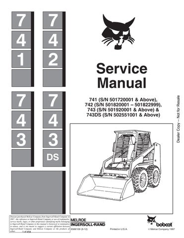
Start the engine and run at 2600 RPM.
The ammeter reading should be between 45 & 55 amps. @ 2600 RPM.
If the reading is low, remove the screws and pull the regulator cover away from the alternator.
Disconnect the battery and connect a jumper wire from the alternator output terminal (Item 1)[B] to the regulator terminal (Item 2) [B]
Connect the battery cable, start the engine and check the ammeter. If the reading is within the rated amperage (45–55 amps. @ 2600 RPM) replace the diode trio.
ALTERNATOR (Cont’d)
Checking The Alternator Regulator (Cont’d)
Connect the positive (+) voltmeter lead to the positive (+) battery terminal and connect the negative (–) voltmeter lead to the negative (–) terminal [A].
Put jackstands under the front axles and rear corners of the frame before running the engine for service. Failure to use jackstands can allow the machine to fall or move and cause injury or death.
When an engine is running in an enclosed area, fresh air must be added to avoid concentration of exhaust fumes. If the engine is stationary, vent the exhaust outside. Exhaust fumes contain odorless, invisible gases which can kill without warning.
Start and run the engine at 1500–2000 RPM. The voltmeter reading should be between 13.9–14.7 volts[A].
If the reading is low, stop the engine and disconnect the battery.
Remove the screws and pull the regulator cover away from the alternator. Connect the jumper wire from the ground stud (Item 1) [B] to the brush terminal (Item 2)[B] (the tan wire).
Connect the battery and start the engine. Run at 1500 RPM. DO NOT allow the meter to exceed 16 volts.
If the reading is 14.5 or above, replace the regulator. If the reading is 14.5 or below, repair or replace the alternator.
MELROE ALTERNATOR (Cont’d)
Removal And Installation
Disconnect the negative cable from the battery. Disconnect the wire terminals from the back of the alternator [A].
Disconnect the battery wire [B]
Remove the adjustment bolt and the mounting bracket bolt.
Remove the alternator.
AVOID INJURY OR DEATH
Never service or adjust the machine when the engine is running unless instructed to do so in the manual.
ALTERNATOR (Cont’d)
Disassembly And Assembly
Disassemble the alternator as shown in figure [A].
Remove the three bolts (Item 4) [A] holding halves together.
Pry the halves apart.
Use a soft jaw vise to hold the rotor while removing the pulley nut (Item 1) [A]
Remove the front case half (Item 5) [A] from the rotor using a plastic hammer or press.
Unsolder the stator wires from the rectifier to test the stator and rectifier. Use a needle nose plier to remove the wires.
Use the following procedures with an ohmmeter to test the rotor:
Touch both probes on the slip rings. There must be a 3 to 5 ohm reading [B]
Touch one probe to the shaft and one probe to a slip ring, then touch the other slip ring. There must be maximum resistance [C]
ALTERNATOR (Cont’d)
Disassembly And Assembly (Cont’d)
Use the following procedure with an ohmmeter to test the stator:
Touch two wire ends of the stator with the probes, take a reading. Move one probe to the other wire. The reading should be the same [A]
Test the ground by touching one probe on the metal surface of the stator and the other probe on the bare wire. There must be no needle movement [B].
Use the following procedure with a circuit tester to test the rectifier:
Touch the positive probe to the positive diode holder and the negative probe to each diode terminal. There must be continuity [C]
Reverse the probes and check the continuity in the other direction. There must be no continuity [D].
ALTERNATOR (Cont’d)
Disassembly And Assembly (Cont’d)
Touch the negative probe to the negativediode holder and the positive probe to each diode terminal. There must be continuity [A].
Reverse the probe and check the continuity in the other direction. There must be no continuity [B]
Check the brushes for wear. The maximum of exposed brushes should be 0.125 inch (3,0 mm).
Replace broken or rusted brush springs.
Reverse the order of disassembly.
Place the rotor in shaft jaws when tightening the shaft nut. Tighten to 50 ft.–lbs. (68 Nm) torque [C]
STARTER Checking The Starter
The key switch must be in the OFF position.
The battery must be at full charge.
The cable connections on the battery must be clean and tight.
Connect a jumper wire between S terminal and BAT terminal [A]
If the starter turns but does notturn the engine, the starter drive has a defect.
Connect a jumper wire between the M terminal and the BAT terminal [B]
If the starter turns, the defect is in the solenoid.
If the starter does not turn, the starter is defective.
Removal And Installation
Disconnect the negative (–) cable from the battery. Mark the wires on the starter and solenoid. Disconnect the wires [C]
Remove the stator mounting bolts [D]
Installation: Tighten the bolts to 25–28 ft.–lbs. (34–38 Nm) torque.
Remove the starter.
STARTER (Cont’d)
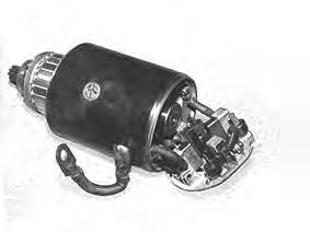
DIRECT DRIVE STARTER
GEAR REDUCTION STARTER
NOTE:Component break down information for the gear reduction starter was unavailable at print date.
STARTER (Cont’d)
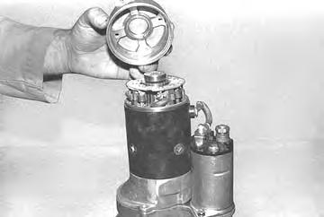
Disassembly And Assembly (Gear Reduction)
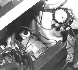
Remove the starter thru–bolts [A].
Remove the screws for the brush holders [B].
Remove the starter end cap [C]
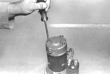
Remove the starter housing/armature assembly from the reduction gear drive [D].
STARTER (Cont’d)
Disassembly And Assembly (Gear Reduction) (Cont’d)
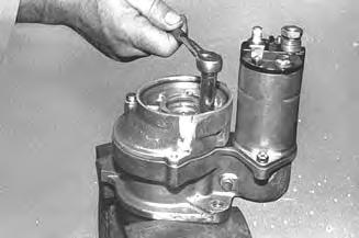
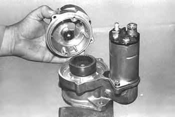
Remove the armature and brushes from the starter housing [A]
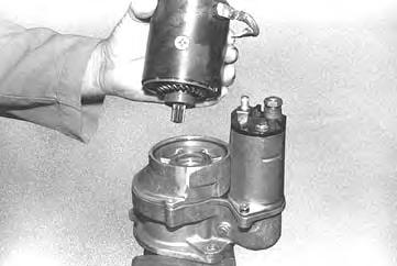
Remove the bolts from the reduction gear housing [B]
Remove the reduction gear housing [C]
Replacing The Brushes
Remove the screws at the brushes [D].
Remove the screws at the brush leads.
Remove the old brushes.
Install the new brushes and make sure to tighten the screws.
Assembly of the starter: Reverse the order of disassembly. Put a small amount of grease on the splines of the armature and the bushings. Add or remove shims at the drive end of the armature to adjust the end play.
STARTER (Cont’d)
Cleaning and Inspection
Use a brush and air pressure toclean the drive, field coils, armature and starter housing. Check the following items:
NOTE:Do not use solvent to clean the drive assembly. The solvent will remove the lubricant and the drive will slip.
Armature
Broken or burned insulation. Loose connections at commutator. Open or grounded circuits [C] & [D] Worn shaft or bearings. Rough commutator.
Brush Holders
Broken springs. Broken insulation. Spring tension.
Field Coils
Broken or burned insulation. Electrical continuity. Brush connections.
Drive Gears
Worn teeth. Tooth engagement.
Field Coils
Broken or burned insulation
Electrical continuity [C]
Brush connections.
Drive Gear: Worn teeth
Tooth engagement (drive gear must engage ring gear by 1/2 the depth of the ring gear tooth)
To test for ground, use a test light and touch one probe to the body and the other probe to the field winding end of the brush. The lamp should not light [D]
Continued On Next Page