47 minute read
VALVE SPRING, RETAINER AND STEM SEAL (With The Cylinder Head Installed) (Cont’d)


Be sure piston is at top dead center or bottom dead center before applying air pressure. If not the engine can turn and cause injury.
W–2264–0897
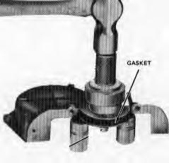
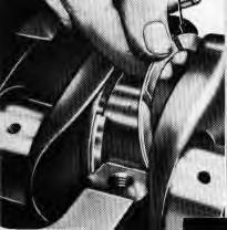
Compress the valve spring, and removethe valve spring, retainer locks. Release the spring compressor remove the valve spring, rotator, retainer and the valve stem to seal.
Install The Valve Spring
Install a new seal over the valve stem. Two types are used. Early engines use an umbrella type (Item 1) [A] Later production engines use pedestal type which fasten the valve stem guide (Item 2) [A]
Install the valve spring and retainer on the valve stem.
Compress the valve spring Put the valve spring retainer locks in the valve stem grooves and release the spring at a slow rate to engage the locks in the retainer. Remove the air hose and adapter.
Put oil on both ends of the pushrods and install the pushrods in the correct bores. Install the rocker shaft assembly to the cylinder head, put the pushrods on the adjustment screws. Tighten the bolts evenly to specifications.
Adjust the valve clearances to specifications.
Install the rocker cover.
Install the spark plugs and connect the wires to the spark plugs in the correct firing order.
Disconnect the wires from the spark plugs and remove the rocker cover.
Make a second adjustment of the valve clearances (hot) to specifications.
Install the rocker cover with a new gasket and tighten the fastening screws to specification.
Put the spark plug wires in the rocker cover fastener and connect them to the correct spark plugs.
Water Pump
Removal
Remove the coolant from the cooling system.
If a new water pump is being installed, move the water hose connection to the new water pump.
Put the water pump and the gasket on the cylinder block and fasten with the bolts.
Connect the manifold water hose the water pump and tighten the clamp.
Connect the lower hose on the water pump and tighten the clamp.
Install the sheave and the fan. Install the bolts and tighten to the correct torque specifications.
Install the drive belt over the crankshaft, fan and governor sheave and make adjustment of the belt tension to specifications. Tighten the governor fasten fastening and adjusting bolt to specifications.
Adjust the governor.
Fill the radiator and install the radiator cap. Start the engine and check for leaks
CYLINDER FRONT COVER, TIMING CHAIN AND CRANKSHAFT SPROCKETS
Removal
Remove the engine coolant by opening the drain valve on the radiator and removing the drain plug in the cylinder block.
Disconnect the radiator hoses from the engine.
Remove the governor belt and remove the water pump sheave.
Remove the water pump.
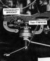
Remove the crankshaft sheave, using a puller.
Remove the four bolts that hold the oil pan to the timing chain cover. Remove the six bolts that hold the timing cover to the cylinder block.
NOTE:Be careful not to cause damage to the oil pan gasket. If the gasket becomes damaged it will benecessary to remove the oil pan and replace the gasket. A damaged gasket will cause an oil leak.
WATER PUMP (Cont’d)
Removing the Timing Cover
Remove the crankshaft oil thrower. Remove the crankshaft sprocket retainer and the bolts.
Remove the timing chain tightening arm. Remove the camshaft sprocket and disconnect the timing chain.
Use a puller to remove the crankshaft sheave [A]
Installation Of The Timing Cover
Install the crankshaft if removed [B]
Install the camshaft sprocket.
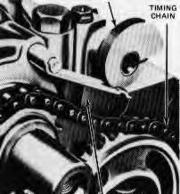
Install the timing chain over the camshaft and crankshaft sprockets so the timing marks are in alignment [C].
Install the camshaft sprocket retainer and the bolts, then tighten the bolts to specification. Bend the locking tabs.
Install the tightening arm on the pivot pin while holding and tightening the cam in the released position.
Install the oil thrower on the crankshaft. Install the timing chain tightener.
Install the timing cover gasket, the oil pan gasket (if needed) and the end seal on the front cover with an oil resistant sealer at the ends. Make alignment of the cover with the tool [D]. Tighten the fastening bolts evenly to specification and remove the alignment tool. Tighten the oil pan bolts to specification.
Install the crankshaft sheave, making alignment of the slot with the crankshaft key. Tighten the fastening bolts to specification.
Install the water pump sheave. Install the governor belt and make adjustment of the tension of the belt to specifications.
Install the radiator hoses and tighten the clamps.
Fill the radiator with coolant.
Start the engine and check for oil and water leaks.
Front Oil Seal
Removal
Remove the timing cover.
Push the seal out from the inside of the cover.
Front Oil Seal
Removal
Remove the timing cover.
Push the seal out from the inside of the cover.
Installation
Push the new seal into the housing [A]. Put a support under the housing near the seal to keep housing from breaking.
When installing the cover it is important that the oil seal is in alignment with the crankshaft and sheave boss.
Timing Chain Tightening
Removal
Remove the timing chain cover (and oil pan if necessary).
Remove the timing chain tightener and arm by removing the two fastening bolts [B]
Installation
Install the tightener arm on the pivot pin. Install the tightener and install the two bolts.
Install the timing chain cover (and oil pan if necessary).
Camshaft And Valve Lifters
Removal
Remove the engine assembly and put the engine on a stand. Remove the crankcase oil.
Disconnect the fuel line at the fuel pump.
Loosen the governor adjustment bolts and remove the belt.
Remove the water pump sheave.
Remove the oil and fuel pumps from the cylinder block.
Disconnect the spark plug wires from the spark plugs and remove the rocker cover. Clean all gasket material from the rocker arm cover and cylinder head.
Remove the distributor from the cylinder block.
Remove the rocker shaft bolts evenly and lift off the rocker shaft.
CAMSHAFT AND VALVE LIFTERS (Cont’d)
Removal (Cont’d)
Remove the pushrods from the cylinder block and keep them in the correct order.
Turn the complete engine over on the stand and remove the oil pan and the gaskets.
Remove the crankshaft sheave. The timing cover and the oil thrower.
Remove the timing chain tightener assembly.
Remove the camshaft sprocket and the timing chain.
Remove the camshaft thrust plate and remove the camshaft [A]
Remove the tappets from the cylinder block and keep them in the correct order.
Installation
Install a new timing cover oil seal. (See Page 7B–27.)
Install the tappets.
Install the camshaft and install the thrust plate in the camshaft groove. Tighten the fastening assembly bolts to specification and bend the locking tabs.
Check the camshaft end play.
Put the timing chain on both sprockets. (Be sure marks on the sprockets are in alignment.) Install the sprockets on the crankshaft and the camshaft then tighten the bolts to specification and bend the locking tabs.
Find the tightener arm on the pivot pin and install the timing chain tightener.
Install the oil thrower on the crankshaft.
Put the gasket on the timing cover with an oil sealer at the end. Make alignment of the front cover and tighten the bolts evenly to specification.
Put a new gasket on the blockflange using an oil resistant sealer compound at each end. Put the end seals (chamfered ends) into the groove, again using an oil resistant sealer at the ends and install the oil pan. Tighten the oil pan bolts 6–8 ft.–lbs. (8–10 Nm) torque [B]. First tighten according to alphabetical order (A–B–C etc.) then tighten according to numerical order (1–2–3).
Install the dipstick.
Install the crankshaft sheave, making alignment of the slot with the crankshaft key. Tighten the sheave fastening bolt to specification.
CAMSHAFT AND VALVE LIFTERS (Cont’d)
Installation (Cont’d)
Turn the engine over on the stand. Install the distributor and adjust the timing.
Install a new gasket on the oil pump mounting flange and install the oil pump and the filter assembly. Tighten the fastening bolt to specification.
Install a new gasket on the fuel pump flange and install the pump lever through the slot in the block so that the lever is on the lobe of the camshaft. Fasten the fuel pump to cylinder block with the two washers and bolts. Tighten the bolts evenly to specifications.
Put oil on the contact surfaces of the pushrods, valve stems and rocker arms. Install the pushrods in the correct bores and install the rocker shaft assembly. Be sure to put the end of the pushrods on the adjustment screws. Tighten the rocker shaft fastening bolts evenly to specification.
Adjust the valve clearance. (See SPECIFICATIONS Section 8B–1.)
Connect the distributor vacuum advance line to the carburetor.
Install the water pump sheave. Install the drive belt on the sheave and make adjustment of the belt tension to specifications. Connect the fuel line from the carburetor to the fuel pump.
Install distributor cap and connect the wires to the spark plugs.
Remove the engine from the stand.
Install the engine assembly in the Bobcat loader.
Start the engine assembly in the Bobcat loader.
Start the engine and check for oil water leaks.
Make a second adjustment of the valve clearances (cold) to specifications.
Install the rocker cover and install a new gasket and fasten with screws. Tighten to specifications.
Start the engine and make adjustment of the ignition timing if needed.
Make adjustment of the carburetor idle speed and fuel air mixture to specifications.
OIL PAN
Removal
Remove the crankcase oil.
Remove the dipstick.
Remove the three bolts and remove the starter. (See Page 7B–41.)
Remove the oil pan fastening bolts and remove the pan and the gasket.
OIL PAN (Cont’d)
Installation
Clean the oil pump inlet tube and the screen assembly. clean the gasket surfaces of the block and the oil pan. Be sure to clean the seal grooves in the timing chain cover and the rear seal retainer. The oil pan has a two piece gasket. Put sealing compound on the block surface and the oil pan gasket surface. Install the oil pan and tighten the bolts evenly to specifications following first the alphabetical, then the numerical steps. (See Page 7B–29.)
Clean and install the starter and fasten it with three bolts. Fill the oil pan with the correct engine oil and install the dipstick.
Oil Pump
The oil pump and filter assembly is installed on the left side of the cylinder block and can be removed with the engine in the machine.
Removal
Put a pan under the oil pump.
Remove the three bolts that hold the oil pump and filter assembly and remove the assembly [A]
Remove the oil filter from the oil pump.
Installation
Install the new oil filter on the oil pump assembly.
Make sure the contact surfaces are clean of the old gasket material, then install the oil pump and the filter assembly on the cylinder block, using a new gasket with sealing compound and fasten with the three bolts. Tighten the bolts to specifications.
Check the oil level and add oil if needed.
Crankshaft Rear Oil Seal
Removal
Remove the flywheel
Remove the oil pan and the gasket.
Remove the rear oil seal carrier and remove the seal.
CRANKSHAFT REAR OIL SEAL (Cont’d)
Installation
Install a new crankshaft rear oil seal [A].
Put a new gasket on the rear oil seal carrier using a sealing compound at the end, and the carrier on the block rear surface. Tighten the bolts evenly to specifications.
Put new gaskets on the block flange using sealing compound at each end. Install the end seals with the chamfered end into the grooves, again using a sealing compound and install the oil pan. Tighten the bolts to the correct torque using the steps in [B].
Install the flywheel on the crankshaft flange. Be sure to contact surfaces of flywheel and crankshaft are clean. Tighten the bolts evenly to specifications.
Main Bearings
The cast iron crankshaft is supported by five bearings.
The main bearing caps must be kept in original position. An arrow in the cap points to the front of the engine location marks are on the caps.
The front bearing cap has the letter F. The second caphas the number 2. The center cap has the letter C. The fourth cap has the number 4. The rear cap does not have a marking.
Removal
Remove the main bearing caps and the thrustwashers. Keep the caps in order so each cap will be installed in its original position.
Remove the bearing halves from the cylinder block and from the caps.
Check the caps and crankshaft for damage.
Install new bearing halves in the cylinder block and from the bearing caps.
Make sure that the crankshaft and the bearings are free from dirt and other debris.
Measure the bearing clearances using Plastigage. (See Page 7B–13.)
Installation
Clean the crankshaft and the bearings.
Install the crankshaft thrustwashers.
Put oil on the bearing surfaces and install the bearing caps in their original positions and tighten the bolts to specifications.
Connecting Rod Bearings
Removal
Turn the crankshaft to remove the number the number one connecting rod cap. Loosen the connecting rod bolts two or three turns and hit the bolts to release the cap. Remove the bolts and remove the cap. Keep the caps in order so each cap will be installed in its original position.
Remove the bearing halves from the connecting rod caps.
Installation
Install the upper and lower bearings in the correct locations.
Measure the bearing clearances using Plastigage. (See Page 7B–13 To Check Crankshaft Or Connecting Rod Bearing.)
Install the connecting rod caps on the connecting rods in their original positions and tighten the bolts to specifications.
Pistons And Connecting Rods
Removal
Remove the engine. (See Page 7B–8.)
Remove the thermostat housing and remove the thermostat.
Remove the rocker cover and the gasket.
Remove the rocker shaft bolts evenly and remove the rocker arm shaft assembly.
Remove the pushrods and keep them in the correct order.
Remove the cylinder head bolts and remove the cylinder head and gasket. Do not put the cylinder head flat on its surface. Damage to the spark plugs or the gasket surface can result.
Remove the starter and the oil pan.
Clean the oil pan and the cylinder block surfaces and remove the end seals.
Loosen the bearing cap bolts several turns and hit the bolts to release the bearing cap. Remove the bolts and remove the bearing cap. Keep the bearing caps in order so each can be installed in its original positions. Pus the piston and the connecting rod out of the bore.
PISTONS AND CONNECTING RODS (Cont’d)
Installation
Install the bearing halves in the connecting rods and the end caps. Turn the crankshaft as needed to fit each connecting to the crankshaft, but do not install the end cap.
Measure the bearing clearances using Plastigage. (See Page 7B–13 To Check Crankshaft Or Connecting Rod Bearing.)
Clean all the bearing surfaces of the Plastigage material. If needed use new rod bearings to correct clearances.
Install the connecting rods on the crankshaft and tighten the connecting rod bolts to specifications.
Install a new gasket on the block flange using sealing compound at each end. Install the end seals with the chamfered ends into the grooves again using sealing compound.
Install the oil pan and tighten the bolts to the correct torque, following the tightening sequence. (See Page 7B–31.)
Clean and install the starter. Fasten the starter with the two bolts.
Clean all the gasket material from the contact surfaces and install the cylinder gasket on the cylinder block using alignment studs.
Install the cylinder head. Remove the alignment studs and install the cylinder head bolts. Tighten the bolts. (See Page 7B–22 Installing The Cylinder Head.)
Put oil on both ends of the pushrods and install the pushrods in the correct bores.
Install the rocker shaft assembly on the cylinder head put the pushrods on the adjustment screws. Tighten the bolts to the correct specifications.
Camshaft Bearings
The service bearings for the camshaft are machines to fit and need no machining after installation. When one bearing needs replacement replace all three bearings to be sure of the correct camshaft alignment.
Make sure that the oil holes in the bearings and the cylinder block are in correct alignment before installation and that the bearing openings are at 45 ° to the vertical [A].
CAMSHAFT BEARINGS (Cont’d)
Removal
Remove the engine. (See Page 7B–8.)
Remove the flywheel.
Remove the crankshaft rear oil seal bracket. (See Page 7B–31.)
Put a new gasket on the rear oil seal bracket using sealing compound at the ends. Install the bracket on the cylinder block and tighten the bolts to specifications.
Install the flywheel on the crankshaft flange. Be sure contact surfaces are clean. Tighten the fastening bolts to specifications.
Install the camshaft.
CRANKSHAFT
Removal
Remove the engine from the Bobcat and put it in an engine stand. (See Page 7B–8.)
Remove the flywheel from the crankshaft.
Loosen the governor fastening bolts and remove the drive belt.
Remove the sheave from the front of the crankshaft.
Remove the front cover.
Remove the oil thrower from the shaft [A]. Remove the timing chain tightener and timing chain. Remove the crankshaft sprocket from the crankshaft.
Turn the engine over, remove the oil pan. Remove the oil inlet tube and the screen.
Remove the four connecting rod bearing caps and keep them in order so that each cap will be installed on the correct rods.
Remove the five main bearing caps and keep them in order so that each will be installed in the correctlocation.
Carefully remove the crankshaft from the cylinder block.
Installation
Install the main bearings in the cylinder block. Install the crankshaft and check the bearing clearance using the Plastigage method. (See Page 7B–13.) Install the correct main bearing caps and tighten to specifications.
Check the crankshaft end play. (See Page 7B–7.)
Install the correct thickness of thrustwashers to give the correct endplay [B]
CRANKSHAFT (Cont’d)
Installation (Cont’d)
Check the connecting rod bearings using the Plastigage method. (See Page 7B–13.)
Install the rod bearings and the correct connecting rod caps in the correct locations and tighten the cap bolts to specifications.
Install the oil inlet tube and the screen.
Install the crankshaft sprocket and timing chain making sure that the timing marks are in alignment.
Install the oil thrower timing chain tightener and timing chain tightener and timing chain cover. Install the crankshaft sheave.
Install the oil pan and new gaskets. Tighten the oil pan fastening bolts to specifications. (See Page 7B–31.)
Turn the engine over again and install the governor drive belt. Make belt adjustment to specified tension. Install the flywheel.
Install the engine in the Bobcat loader.
Fill the crankcase and the cooling system to the correct level with the specified oil and coolant. Start the engine and check for oil and water leaks.
Universal Joint
The tool listed will be needed to do the following procedure:
MEL1187 – Socket
Removal
Remove the engine. (See Page 7B–8.)
Remove the bolts (Item 1) [A], holding the u–joint on the flywheel. Remove the u–joint assembly.
Installation
Put LOCTITE on the four bolts. Install the u–joint. Install the bolts and tighten to 270–300 in.–lbs. (31–34 Nm) torque. Put spline lube (MEL1121) on the splines before installation.
Flywheel
Removal
Remove the bolts that attach the blower fan to the flywheel (Item 2) [A]. Remove the blower fan.
Remove the bolts holding the flywheel onto the crankshaft.
Installation: Tighten the bolts to 45–50 ft.–lbs. (61–68 Nm) torque.
Remove the flywheel. Installation is the reverse of removal.
Flywheel Ring Gear
Removal
• When fluids are under pressure.
• Flying debris or loose material is present.
• Engine is running.
• Tools are being used.
Wear safety glasses to prevent eye injury when any of the following conditions exist: W–2019–1285
Cut between the teeth with a hacksaw. Use a chisel to break the ring gear.
Installation
Heat the ring gear to a temperature of not more than 600°F (315°C). Temperature of more than 600° will cause damage to hardness of the ring gear.
Install the hot ring gear on the flywheel.
MUFFLER
Removal
Remove the rear grill.
Remove the exhaust pipe from the muffler [A].
Remove the bolts holding the muffler on [B]
Installation is the reverse of removal.
RADIATOR
Removal
Remove the panel from the blower housing [C]
Loosen the hose clamp on the overflow tube [D]
RADIATOR (Cont’d)
Removal (Cont’d)
Loosen the clamp on the overflow tube by the recovery tank and remove the tank [A]
Remove the overflow tube [B].
Remove the muffler exhaust pipe.
Remove the inlet radiator hose [C]
Remove the outlet radiator hose [D]
RADIATOR (Cont’d)
Removal (Cont’d)
Remove both the inlet and the outlet tubelines from the oil cooler [A]
Remove the right mounting bolt for the radiator assembly [B]
Remove the left mounting bolt for the radiator assembly [C]
RADIATOR (Cont’d)
Removal (Cont’d)
Remove the radiator assembly [A].
Remove the radiator mounting bolts [B].
Remove the radiator from the assembly.
Installation
Install the mounting bolts [B].
Tighten the mounting bolts 180–200 in.–lbs. (21–23 Nm) torque.
Install the radiator assembly [A].
Install the assembly mounting bolts (See Page 7B–38.)
Tighten the bolts 180–200 in.–lbs. (21–23 Nm) torque.
Install the tubelines to the oil cooler.
Install the two radiator hoses.
Install the muffler exhaust pipe.
Install the overflow tube and the coolant recovery tank.
Connect the overflow tube at both ends and tighten the hose clamps.
Install the panel on the blower housing. Tighten the bolts to 180–200 in.–lbs. (21–23 Nm) torque.
Blower Housing
Removal
Remove the engine. (See Page 7B–8.)
Remove the radiator, oil cooler assembly. (See Page 7B–36.)
Disconnect the fuel lines from the fuel filter [C].
Removal
Disconnect the battery cables (negative (–) battery cable first).
Remove the wires from the starter [A]. Make note of the wire connections to make sure the wires are connected correctly during assembly.
Remove the starter mounting bolts [B]
Remove the starter [C]
Installation
Install the starter.
Install the mounting bolts and tighten to 25–28 ft.–lbs. (34–38 Nm) torque.
Connect the wires to the correct terminals [A]
TROUBLESHOOTING Chart
The following troubleshooting chart is provided for assistance in locatingand correcting problems which are most common. Many of the recommended procedures must be done by authorized Bobcat Service Personnel only.
Problem
Engine will not turn over with the starter.
Engine will not start or is difficult to start.
Engine misses, runs irregularly or stops.
Engine overheats.
To much engine vibration. 29, 30
Key To Correct The Cause
1.Battery has lost its charge.
2.Loose battery connections.
3.Loose starter connections.
4.Damaged starter switch.
5.Broken starter switch.
6.Damaged starter solenoid.
7.Wrong starting procedure.
8.No fuel in tank.
9.Air cleaner is dirty.
10.Fuel vent in cap has restriction.
11.Fuel line has air leak, dirt or water.
12.Damaged fuel lift pump.
13.Hydraulic/Hydrostatic load on engine.
14.Damage to fuel injection system.
15.Crankcase oil is thick.
16.Check glow plugs.
17.Check pre–heat solenoid.
18.Check the fuel shutoff button.
19.Delivery valve nuts not tightened.
20.Fuel injection set wrong.
21.Dirty fuel, or fuel filter restricted.
22.Poor compression.
23.Wrong fuel (use diesel only).
24.Water in the fuel.
25.Engine is overloaded.
26.Dirty engine oil.
27.Exhaust system has restriction.
28.Injection timing is wrong.
29.Loose engine mounts.
30.Worn rubber mounts.
FUEL FILTER Replacing The Fuel Filter
The fuel filter is on the right hand side of the engine on the main frame. Replace the fuel filter every 250 hours of loader operation.
To replace the fuel filter element: Clean the filter areas.
Shut off the fuel at the fuel tank.
Remove the bolt from the top of the filter housing (Item1) [A]
Remove the element and the rubber seal from the housing.
Install a new rubber seal on the housing and put a small amount of oil on the rubber seal.
Install the new filter element in the container and install on the filter head. Hand tighten only.
Open the fuel shutoff valve at the tank until the fuel filter container is full.
Tighten the bolt to prevent leakage.
Removing Air From The Fuel System
After replacing of the fuel filter element or when the fuel tank has run out of fuel, the airmust be removed from the fuel system before starting the engine.
Open the rear door. The engine must be cool.
Open the vent plug (Item 2) [A]
Operate the hand pump (Item 3) [A] until fuel flows from the vent plug (Item 2) [A] with no air bubbles.
Tighten the vent plug.
Operate the hand pump until it feels solid.
Move the throttle control to minimum RPM. Loosen the valve (Item 1) [B]
Start the engine. When the engine runs smoothly, close the valve (Item 1) [B]
Glow Plug
Checking
Disconnect the glow plug cables and leads.
Remove the glow plug from the cylinder head.
Connect a circuit tester, one terminal to each end of the glow plug [C]
The reading must be approximately 1.5 ohms. If the resistance is zero ohms the glow plug has a short circuit. If the resistance is infinite the coil of the glow plug is broken.
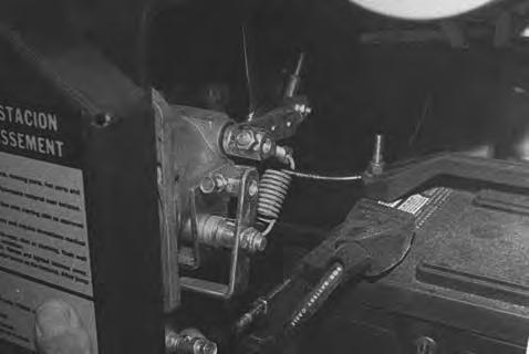
Fuel Injection Pump
The injection pump contains parts which have a very close tolerance and its operation has a directeffect on the performance of the engine.
Do not attempt to maintain or adjust unless you are trained and have the correct equipment.
I–2028–0289
Removal and Installation
Clean the area around the injection pump. Disconnect the fuel shut–off linkage (Item 1) [A]
Disconnect the fuel inlet hoses (Item 2) [A]
Disconnect the high pressure tubelines (Item 3) [A]
Installation: Tighten the delivery valve nuts to 29–36 ft.–lbs. (39–48 Nm) torque.
Do not bend the high pressure fuel injection tubes when removing or installing them.
I–2029–0289
Remove the side cover (Item 4) [A]
Remove the four mounting nuts.
Installation: Tighten the nuts to 17–20 ft.–lbs. (23–27 Nm) torque.
Put the pin in the control rack inalignment with the slot in the engine block (Item 1)[B]. Remove the injection pump.
NOTE:Make sure the same number of shims are installed under the injection pump. The shims are used for engine timing.
Installation: When the injection pump is installed, make sure the pin (Item 2) [B] on the control rack is correctly installed on the fork lever. If the slot is not installed correctly, the engine will run over maximum speed and serious damage can result.
FUEL INJECTION PUMP (Cont’d)
Timing The Injection Pump
Timing of the fuel system is done by changing thenumber of shims between the injection pump and the engine block, The timing of the fuel injection pump will be later when a shim is added, and earlier when a shim si removed.
Diesel fuel or hydraulic fluid under pressure can penetrate skin or eyes, causing serious injury or death. Fluid leaks under pressure may not be visible. Use a piece of cardboard orwood to find leaks. Do not use your bare hand. Wear safety goggles. If fluid enters skin or eyes, get immediate medical attention from a physician familiar with this injury.
Remove the number 1 cylinder injector tubeline from the injector pump.
Install a short pipe to the outlet of the number 1 cylinder injector port. Point the pipe up (vertical).
With a fuel supply to the injection pump, rotate the engine in a clockwise direction. Fuel must flow from the pipe when the fixed mark F–1 on the crankshaft pulley and the point comes into alignment [A]
The correct timing for the engine is 25 degrees B.T.D.C. (#1 cylinder). Add or subtract shims (Item 1) [B] as needed to adjust the delivery time of the fuel. Each shim will change the timing 1.5 degrees.
FUEL INJECTION PUMP (Cont’d) Checking The Injection Pump
The tools listed will be needed to do the following procedure:
MEL1237 – Adapter Fuel Line
MEL1173–1 – Pressure Gauge
To check the discharge pressure at the fuel injection pump, use the following procedure:
Disconnect a high pressure fuel line (Item 1) [A] at the pump. Loosen the other end of the same high pressure line so it can be turned away from the fitting.
Connect the adapter fuel line (Item 1) [B] to the fitting.
Connect the pressure gauge (Item 2) [B].
Rotate the engine, with the starter, until the pressure raises. Then turn the engine by hand until the pressure gauge reads 1400 PSI (9653 kPa).
Align F1 on crankshaft pulley.
The injection pump must hold the 1400 PSI (9653 kPa) for at least 5 seconds. If not, replace or repair the injection pump.
Diesel fuel or hydraulic fluid under pressure can penetrate skin or eyes, causing serious injury or death. Fluid leaks under pressure may not be visible. Use a piece of cardboard orwood to find leaks. Do not use your bare hand. Wear safety goggles. If fluid enters skin or eyes, get immediate medical attention from a physician familiar with this injury.
Some problems caused by faulty injector nozzles:
The engine is hard to start or will not start. Rough engine operation and idle. The engine will not have full power. The engine exhaust smoke is black, white or blue.
Removal And Installation
The tool listed will be needed to do the following procedure:
MEL1181 – Nozzle Wrench
Do not bend the high pressure fuel injection tubes when removing or installing them.
Disconnect the high pressure fuel lines at the fuel injector [A]
Disconnect the high pressure fuel lines at the injection pump [B]
Remove the high pressure lines [C]
Disconnect the low pressure hoses (Item 1) [D] at the injectors.
Use the special tool and remove the fuel injector from the cylinder head.
Installation: Tighten the delivery valve nuts (Item 1) [B] to 29–36 ft.–lbs. (39–49 Nm) torque.
Tighten the nozzle holder to 22–36 ft.–lbs. (30–29 Nm) in the cylinder head.
FUEL INJECTOR NOZZLES (Cont’d)
Checking the Nozzles
You can adjust the release pressure of the injector by adding or removing spacers (Item 1) [A] at the top of the nozzle spring (Item 2) [A].
Each 0.0039 inch (0,01 mm) spacer will change the release pressure about 142 PSI (979 kPa). The release pressure must be 1920–2133 PSI (13238–14707 kPa).
Connect the injector nozzle to the tester with the nozzle down.
Use tools MEL10018 & MEL10019.
Operate the hand lever at a slow rate and not the opening pressure.
If the pressure is not correct, disassemble the injector nozzle and add or remove spacers.
Assemble the injector nozzle and check the pressure again.
When you assemble the injector nozzle, tighten the nozzle body (Item 3) [A] to 43–58 ft.–lbs. (59–79 Nm) torque.
NOTE:Do not over tighten, or slow action of the valve will occur.
Check for inside leakage. Operate the hand lever untilthe pressure is almost enough to open the injector valve. Record the pressure.
Release the hand lever. Check the pressure decrease for 10 seconds.
If the pressure decrease is more than 740PSI (5102 kPa) in 10 seconds, the nozzle is damaged.
Check that the spray pattern is correct [B]
The spray pattern is not correct if any of the following occur:
Fuel comes out of the side of the nozzle.
Drops of fuel are present at the nozzle.
The nozzle does not have an even flow coming from the nozzle.
Do not disassemble or test the injector nozzles unless you have the correct service and testing tools.
Diesel fuel or hydraulic fluid under pressure can penetrate skin or eyes, causing serious injury or death. Fluid leaks under pressure may not be visible. Use a piece of cardboard orwood to find leaks. Do not use your bare hand. Wear safety goggles. If fluid enters skin or eyes, get immediate medical attention from a physician familiar with this injury.
Engine
Removal
Open the rear door and clean the engine area.
Disconnect the battery cables, ground cable first. (See ELECTRICAL SYSTEM Section 6.)
Remove the coolant from the engine. The radiator cap must be loosened to drain coolant.
Connect a hose to the valve or use a funnel to keep coolant from getting into the engine compartment. Open the valve (Item 1) [A] and drain coolant into a container.
Turn the lever (Item 1) [A] on the valve. When all the coolant is removed close the valve.
Close the shutoff valve.
Remove the exhaust pipe from the manifold [B]
Remove the radiator hoses [C]
Remove the fuel return hose [D].
ENGINE (Cont’d)
Removal (Cont’d)
Remove the hot wire from the starter [A]
Remove the electrical wire from the solenoid [B]
Remove the fuel inlet line at the fuel filter.
Remove the air cleaner hose [C]
Remove the throttle linkage [D].
ENGINE (Cont’d)
Removal (Cont’d)
Disconnect the engine harness at the connector [A]
Remove the spring clamp from the fuel shutoff cable [B]
Remove the cable from the speed control arm [C].
Remove the engine mounting bolts [D]
ENGINE (Cont’d) Installation
Raise the operator cab.
Put the engine in the loader.
Have a second person in the pump area. Align the coupler on the engine flywheel to the splined shaft on the hydrostatic motor by turning the engine with the tool listed.
MEL1234 – Crankshaft Nut Socket
NOTE:Belt shield must be removed.
Install the engine mount bolts and tighten to 65–70 ft.–lbs. (88–95 Nm) torque.
Install all other parts removed.
Radiator And Oil Cooler
Removal And Installation
Remove the panel from the blower housing [A].
Loosen the hose clamp on the overflow hose [B]
Drain the coolant tank and loosen the clamp on the overflow hose by the recovery tank and remove the tank [C]
Remove the overflow hose [D].
Remove the muffler exhaust pipe.
RADIATOR AND OIL COOLER (Cont’d)
Removal And Installation (Cont’d)
Drain the coolant and remove the inlet radiator hose [A].
A
B–04764
Remove the outlet radiator hose [B]
Remove both the inlet and the outlet tubelines from the oil cooler [C]
Remove the mounting bolts for theradiator assembly [D].
RADIATOR AND OIL COOLER (Cont’d)
Removal And Installation (Cont’d)
Remove the radiator assembly [A]
Remove the radiator mounting bolts [B]
Remove the radiator.
Remove the oil cooler mounting bolts (Item 1) [B]
Installation: Fill the radiator with premixed coolant and install the radiator.
Install the grill. Fill the coolant recover tank 1/3 full with premixed coolant.
Blower Housing
Removal And Installation
Remove the engine. (See Page 7C–8.)
Remove the radiator, oil cooler assembly. (See Page 7C–12.)
Disconnect the fuel lines from the fuel filter [A].
Remove the center nut from the blower housing [B]
Remove the bottom bolt from the blower housing [C]
Remove the blower housing [D]
ENGINE FLYWHEEL AND U–JOINT Removal And Installation
Remove the engine. (See Page 7C–8.)
Remove the four bolts at the u–joint mounting flange[A].
Installation: Put LOCTITE on the four bolts. Tighten the bolts to 25–28 ft.–lbs. (43–48 Nm) torque.
Remove the u–joint from the flywheel [B].
MEL1187 – Socket
Bend the locking tabs away from the bolt flats [C]
Installation: Bend the locking tabs against the bolt flats.
Remove the flywheel bolts [D].
Installation: Tighten the bolts to 72–80 ft.–lbs. (98–108 Nm) torque.
Flywheel Ring Gear
The ring gear on the flywheel is an interference fit. Heat the ring gear enough to expand it and hit it with a hammer, evenly to remove it.
Clean the outer surface of the flywheel to give a smooth fit.
Clean the new ring gear and heat it to a temperature of 450–500°F (232–260°C).
Fit the ring gear over the flywheel. Make sure the gear is on its seat correctly.
Muffler
Removal And Installation
Remove the rear grill.
Remove the exhaust pipe from the muffler [A]
Remove the bolts holding the muffler [B]
CYLINDER HEAD Removal
Remove the nuts from the valve cover and remove the valve cover [A]
Disconnect the injector tubelines.
Remove the injector nozzles and the copper gasket [B]
Remove the intake manifold.
Remove the belt shield and remove the alternator.
Remove the rocker arm [C]
Remove the push rods.
Remove the water return pipe.
Remove the cylinder head bolts.
Remove the cylinder head [D]
Remove the cylinder head gasket and the O–rings.
CYLINDER HEAD (Cont’d)
Disassembly
NOTE:There may be a shim under the head gasket. Use the shim over again or replace it with the same size shim.
Remove the valve cap (Item 1) [A] and the valve spring collet (Item 2) [A]
Remove the valve spring retainer (Item 3) [A]
Remove the spring (Item 4) [A]
Remove the seal (Item 5) [A] and the valve (Item 6) [A]
Remove the thermostat [B]
Servicing
Use the tool listed for the following procedure:
MEL1098 – Valve Lapper
Clean the surface of the cylinder head.
Put a straight edge (Item 1) [C] on the cylinder head.
NOTE:Do not put the straight edge across the combustion chamber.
Put a feeler gauge (Item 2)[C] between the straight edge and the surface of the cylinder head.
The maximum distortion of the cylinder head surface is ± 0.002 inch (± 0,005 mm).
If the measurement is more than the specifications, the cylinder head must be planed.
NOTE:Place a soft brass rod through the injector hole and tap the combustion chamber out before planing the head. Plane the same amount from the bottom side of the combustion chamber before installing it back in the head.
Clean the valve surface.
Measure the width of the valve seat [D].
CYLINDER HEAD (Cont’d)
Servicing (Cont’d)
The correct width of the valve seat is 0.0827 inch (2,1 mm) and the seat angle is 45 degrees.
Grind the valve seats as follows:
Use a 45° cutter to grind the surface of the valve seat[A]
Use a 15° cutter to grind the front surface of the valve seat [A]
Use a 65° or 75 ° cutter to grind the rear surface of the valve seat to finish the seat to a 0.0827 inch (2,1 mm) width [A].
Grind the valve surface to a 45 ° angle.
Install the valve in the seat and check the depth [B]
The specifications for the depth of the valve is 0.0433–0.0512 inch (1,1–1,3 mm).
If the measurement is more than the specification, add the correct thickness of the washer under the valve spring to keep the correct tension on the spring.
Clean the valve guide.
Install the valve in the cylinder head.
Install the dial indicator.
Measure the clearance of the valve guide and the valve [C]
The measurement must be 0.0016–0.0023 inch (0,04–0,06 mm).
If the measurement exceeds the limit, replace the valve guide. (See Page 7C–21 for Valve Guide Installation.)
Ream the new guide to the correct dimensions.
Measure the valve spring. The length of the spring must be 1.6417–1.6614 inch (41,7–42,2 mm).
Replace the valve spring if it does not meet these specifications.
Check the valve spring with a combination square to make sure it stands straight.
Replace it if is not straight [D].
CYLINDER HEAD (Cont’d)
Servicing (Cont’d)
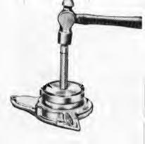
Put the valve spring in a tester [A]
Push down on the spring 1.3839 inch (35,15 mm). The compression load must be 22.5–26.5 lbs. (100–118 N).
Replace the valve spring if it does not meet these specifications.
Measure the inside diameter of the rocker arm bushing (Item 1) [B] and the shaft diameter (Item 2) [B].
The inside of the rocker bushing is 0.5513–0.5529 inch (14,0–14,04 mm).
If the measurements are not within the specifications replace the needed parts.
Valve Guide Installation
Use the tools listed to replace the valve guides:
Press–fit tool
Auxiliary fitting
Margin adjustment jig
See figure [C] for dimensions to make the press–fit tool.
See figure [D] for dimensions to make the auxiliary fitting.
CYLINDER HEAD (Cont’d)
Valve Guide Installation (Cont’d)
See figure [A] for dimensions to make the margin adjustment jig.
Use the following procedure to replace exhaust (Item 1) [B] and inlet (Item 2) [B] valve guides.
Remove the cylinder head. (See Page 7C–18.)
Ream the new valve guide to the correct dimensions.
Use the press–fit tool to remove the old valve guide from the cylinder head.
Slide the auxiliary fitting (Item 1) [C] over the narrow end of the press–fit tool until it makes contact with the middle section of the tool.
Slide the valve guide (Item 2) [C] over the narrow end of the press–fit tool until it makes contact with the auxiliary fitting.
Position the margin adjustment jig (Item 3) [C] above the valve guide hole.
Press the valve guide into the valve guide hole until the auxiliary fitting meets the margin adjustment jig.
The amount of valve guide protrusion will be thickness of the margin adjustment jig which is 0.394 inch(10,0 mm).
CYLINDER HEAD (Cont’d) Assembly
Install the valves.
Put oil in the valve seal and install the seal on the valve.
Install the valve spring and retainer.
Install the spring collet and the valve cap.
Install the thermostat.
NOTE:If a new cylinder head is installed be sure to install the screw plugs which are shipped with the new cylinder head.
Installation
Install a new gasket and O–ring. Install a shim if there was one removed.
Install the cylinder head on the engine block.
Put oil on the bolts and nuts and tighten to the following torque:
Flange Head Bolt65–68 ft.–lbs. (88–92 Nm) . . . . . . . . .
Bolt W/Washer 58–61 ft.–lbs. (79–83 Nm) . . . . . . . . . . .
Use the tightening sequence as shown [A].
Lower the piston which is to be measured for the clearance, between the cylinder head and the piston.
Put a piece of solder in the injector port.
Make sure the solder does not touch the valves [B]
Turn the engine manually.
Remove the solder and measure it. The thickness must be 0.028–0.035 inch (0,7–0,9 mm).
If the measurement is not in the specifications, remove the cylinder head and add the correct shim between the cylinder head the engine block.
Install the cylinder head and tighten the bolts and nut[A].
NOTE:Be sure to torque the bolts and nuts again after the engine has been operated for 30 minutes.
Install the push rods.
Install the water return pipe.
Install the rocker arms.
Tighten the rocker arm holding nuts to 15 ft.–lbs. (20Nm) torque.
Install the alternator, belt and shield.
Install the intake manifold.
Install the injector nozzle with a new copper gasket. Tighten to 22–36 ft.–lbs. (30–49 mm) torque.
Install the injector tubelines.
Adjust the valve clearance. Make sure the piston is at T.D.C. when making the adjustment [C]
Install the valve cover.
0.0057–0.0073 in. (0,145–0,185 mm)
Engine Repair
Remove the cylinder head. (See Page 7C–18.)
Remove the push rods.
Remove the starter. (See ELECTRICAL SYSTEM Section 6.)
Remove the injector pump. (See Page 7C–3.)
Gearcase Removal
Remove the governor spring from the governor fork [A] & [B].
Remove the plate (Item 1) [C] for speed control and the governor spring (Item 2) [C]
Remove the valve tappets [D].
ENGINE REPAIR (Cont’d)
Gearcase Removal (Cont’d)
Remove the start spring from the gearcase [A] & [B].
Straighten the washer on the crankshaft sheave.Remove the nut and washer.
Installation: Tighten the nut to 101–110 ft.–lbs. (137–149 Nm) torque.
After installation, bend the washer on the sheave.
The tool listed will be needed for the following procedure:
MEL1234 – Crankshaft Nut Socket
Use a puller and remove the engine crankshaft sheave [C]
Remove the key.
Remove the bolts from the gearcase.
Remove the gearcase [D].
ENGINE REPAIR (Cont’d)
Timing Gear, Camshaft And Oil Pump Removal
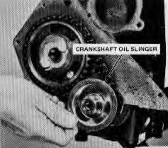
Remove the crankshaft collar (Item 1) [A], O–ring, oil slinger and the gear collar.
Remove the snap ring on the idler gear.
Remove the idler gear (Item 1) [B]
Remove the idler gear collar (Item 2) [B] from the shaft.
Straighten the washer on the bolt for the camshaft stop.
Remove the bolt for the camshaft stop.
Remove the camshaft [C].
Remove the three bolts that hold the fork lever on the fuel camshaft.
Remove the stop for the fuel camshaft.
Remove the fuel camshaft and the fork lever at the same time [D].
ENGINE REPAIR (Cont’d)
Timing Gear, Camshaft And Oil Pump Removal (Cont’d)
Remove the crankshaft gear with a puller [A]
Remove the key.
Straighten the washer on the gear of the oil pump.
Remove the bolt on the gear of the oil pump.
Remove the gear pump (Item 1) [B].
Remove the oil pump bolt.
Remove the oil pump (Item 2) [B]
Pistons And Crankshaft Removal
Remove the oil pan.
Remove the screen [C]
NOTE:Do not damage the O–ring.
Straighten the washer on the connecting rod bolts.
Remove the connecting rod bolts.
NOTE:Two types of bolts are used [D]. Install in matched pairs only. Do not mix on same rod.
Remove the cap and the bearing from the connectingrod [C]
Installation: Tighten the rod cap bolts to torque as follows:
Machine Bolt (13 mm size head0 27–31 ft.–lbs. (37–42 Nm)
Forged Bolt (12 mm size head) 33–36 ft.–lbs. (45–49 Nm)
ENGINE REPAIR (Cont’d)
Piston And Crankshaft Removal (Cont’d)
Remove the piston from the engine block [A].
NOTE:Be sure the pistons are marked so they willbe returned to the same cylinder.
Straighten the washer on the flywheel bolts.
Remove the bolts from the flywheel.
Use a puller to remove the flywheel.
Straighten the washer on the bolts that hold the main bearing in position.
Remove the main bearing bolts from the engine block[B]
Installation: Tighten the main bearing bolts to 47–51 ft.–lbs. (64–69 Nm) torque.
Straighten the washer on the bolts that hold the main bearings in position.
Remove the bolts.
Install two bolts in the rear cover and pull the cover out [C]
Remove the crankshaft from the rear of the engine [D].
NOTE:Do not damage the crankshaft when removing it from the engine block.
Straighten the washer on the bolts of the main bearings.
ENGINE REPAIR (Cont’d)
Piston And Crankshaft Removal (Cont’d)
Remove the bolts from the bearing cap halves [A].
Remove the halves of the main bearings.
NOTE:When installing the bearing cap halves, make sure to position the markings on the bearing caps toward the flywheel. Thrust washers must be installed with oil grooves facing outward.
Timing Gear And Camshaft Service
Measure the camshaft bearing in the engine block [B].
The specification is 1.5748–1.5758 inches (40–40,03 mm). The wear limit is 0.002–0.0036 (0,05–0,09 mm).
Measure the camshaft journal [C]
The specification is 1.5722–1.5728 inches (39,934–39,950 mm). The wear limit is 0.002–0.0036 inch (0,05–0,09 mm).
If the measurements are not within the specifications replace the needed parts.
Put the camshaft on V–blocks.
Put a dial indicator on the journals.
Turn the camshaft at a slow rate.
The wear limit is 0.0008 inch (0,02 mm) [D]
If the camshaft measurements are not within the specification replace the needed parts.
ENGINE REPAIR (Cont’d)
Timing Gear And Camshaft Service (Cont’d)
Make a measurement of the highest point on each camshaft lobe [A]
The specifications are 1.3134 inches (33,36 mm).
The wear limit is 1.3115 inches (33,31 mm).
NOTE:After the crankshaft is installed, check the clearance for the camshaft gear.
Install a dial gauge.
Hold one gear while turning the other gear [B].
The specification is 0.006–0.0045 inches (0,15–0,11 mm). The wear limit is 0.0118 inch (0,3 mm).
Servicing The Connecting Rods And Pistons
Remove the piston rings (Item 1) [C]
Remove the piston pin (Item 2) [C]
NOTE:Make sure to mark the piston and the connecting rod so they will be assembled correctly [D].
ENGINE REPAIR (Cont’d)
Servicing The Connecting Rods And Pistons (Cont’d)
Measure the piston pin hole [A]
The specifications are 0.9055–0.9060 inch (23–23,013 mm). The wear limit is 0.9076 inch (23,053 mm).
Measure the piston pin (Item 1) [B] and the connecting rod busing (Item 2) [B]
The clearance specification is 0.0006–0.0026 inch (0,0015–0,07 mm).
The allowable limit is 0.0059 inch (0,149 mm) If the clearance exceeds the allowable limit, replace the part.
NOTE:When the replacement bushing is installed, be sure to drill the oil hole in the bushing. De–burr the hole after drilling [B].
Put the piston ring on the bottom of the cylinder.
Check the clearance of the ring gap [C]
The specification is 0.0018–0.0177 inch (0,046–0,45 mm). The wear limit is 0.0492 inch (1,25 mm).
Install the connecting rod on the tool for checking connecting rod alignment.
Check the clearance at the piston pin area [D].
The specifications are 0.0008 inch ( 0,02 mm).
The wear limit is 0.0020 inch (0,05 mm).
NOTE:Be sure the bushing diameter of the connecting rod is within specification.
ENGINE REPAIR (Cont’d)
Crankshaft Service
NOTE:If a new crankshaft is used, besure the plugs that come with the crankshaft are installed in the crankshaft or engine damage will occur.
Put the crankshaft on V–blocks.
Put a dial indicator on the center journal and turn the crankshaft slowly [A]
The specifications are 0.0008 inch (0,02 mm).
The wear limit is 0.0031 inch (0,08 mm).
Check the inside diameter of the crankshaft bearing in the engine block [B]
The specification is 2.0465–2.0488 inches (51,98–52,039 mm). The wear limit is 0.0079 inch (0,2 mm).
Check the outside diameter of the #1 crankshaft journal [C]
The specification is 2.0441–2.0449 inches (51,92–51,94 mm). The wear limit is 0.0079 inch (0,2 mm).
Check the connecting rod bearings [D]
The specifications are 1.7327–1.7343 inches (44,01–44,05 mm). The wear limit is 0.0079 inch (0,2 mm).
ENGINE REPAIR (Cont’d)
Crankshaft Service (Cont’d)
Check the connecting rod journals [A].
The specifications are 1.7307–1.7313 inches (43,959–43,975 mm). The wear limit is 0.0079 inch (0,2 mm).
If the connecting rod journals are not within specifications grind the journals as follows [B] a.Crankshaft corner radius must be 0.127R inch ± .0079 inch (3,5R ± 0,2 mm). b.The oil hole must be chamfered to 0.0394–0.0591R inch (1,0–1,5R mm).
Install the crankshaft and check the end play [C]
Normal end play is 0.0059–0.0122 inch (0,15–0,31 mm). Replace the thrust bearings on the main bearing if end play exceeds 0.020 inch (0,5 mm).
Cylinder Liner Service
Check the inside diameter of the cylinder liner [D]
The tools listed will be used for the following procedure:
MEL1060 – Ridge Reamer
MEL1180 – Dry Liner Puller
ENGINE REPAIR (Cont’d)
Cylinder Liner Service (Cont’d)
To find the maximum wear check the inside diameter in three different locations [A]
The specifications are 3.2283–3.2292 inches(82–82,021 mm). The wear limit is + 0.0059 inch (+ 0,15 mm).
When the cylinder liner has more wear than specifications, bore and hone the cylinder to 3.2480–3.2489 inches (82,499–82,522 mm).
NOTE:Make sure you use the correct oversize pistons and rings.
If the cylinder liner is not within the specifications, replace the cylinder liner. These are dry liners.
Remove the cylinder liners.
Clean and rub oil in the bores of the engine block.
Clean and put oil on the outside of the cylinder liners. Install the cylinder liners into the engine block with the inside and outside diameter chamfered end down.
The top of the liner must be even with the top of the engine block machined surface.
After installation bore and hone the cylinder liner to 3.2283–3.2291 inches (82–82,019 mm).
Lubrication System
The lubrication system consists of a trochoid rotor–type driven oil pump, oil filter cartridge, oil pressureregulating valve, oil switch, and oil filter [B]
Oil is siphoned by the oil pump (b) from the oil pan (o) through the oil filter (a), where the oil is kept at 41–64 PSI (290–441 kPa) by an oil pressure regulating valve (c) installed in the gearcase. The oil flows towards the filter cartridge where it will be further filtered. To insure the supply of lubricating oil, a by–pass valve (d) is provided, the valve opens when the filter element (e) is restricted from the filter cartridge, the pressurized oil is then distributed into two area; some will be fed through crankshaft passages to the crank pin bearing and the rest to the rocker arm shaft (i) through the frame. Oil then returns to the oil pan by gravity.
The oil pressure switch(m) will indicate when oil pressure drops below 7 PSI (48 kPa). The oil pressure switch is connected to the oil pressure gauge in the dash panel. If the pressure reads low or zero while the engine is in normal operation, stop the engine immediately andcheck the oil level.
(a)Pump Screen
(b)Oil Pump
(c)Pressure Regulating Valve
(d)By–Pass Valve
(e)Filter Element
(f)Crankshaft
(g)Piston
(h)Idle Gear
(i)Rocker Arm Shaft (j)Rocker Arm
Rod
Pressure Switch
ENGINE REPAIR (Cont’d)
Oil Pump Service
Check the clearance between the inner and outer rotor [A]
The clearance for the inner rotor is 0.0039–0.0063 inches (0,099–0,160 mm). The wear limit is 0.0079 inch (0,2 mm).
Check the clearance between the outer rotor and the body of the oil pump [B]
The clearance for the outer rotor is 0.0043–0.0075 inches (0,11–0,19 mm).
At full rated engine speed, the normal oil pressure is 42–56 PSI (290–386 kPa) and a minimum of 35 PSI (241 kPa).
Water Pump Service
Remove the water pump from the gearcase [C]
Put the water pump is a vise and remove the nut [D]
Remove the pulley using a puller.
Remove the key.
Remove the snap ring.
ENGINE REPAIR (Cont’d)
Water Pump Service (Cont’d)
Drive the shaft out of the impeller side [A].
Install the new seal [B].
Install the shaft
Put the water pump in a vise and tighten the nut to 50–57 ft.–lbs. (68–77 Nm) torque.
Install the water pump assembly on the gearcase with a new gasket.
Engine Assembly
Crankshaft Installation
Install the main bearing case on the crankshaft journals with marks toward the flywheel end.
Tighten the bolts to 21–25 ft.–lbs. (28–34 Nm) torque.
Install the thrust bearing with the oil grooves to the outside.
Install the crankshaft in the engine block.
Each main bearing is numbered for correct location.
Make sure the oil holes in the main bearings are in alignment with the holes in the engine block [A]
Install the main bearing case bolts and tighten to 47–50 ft.–lbs. (64–68 Nm) torque.
Install new seals int he crankshaft rear cover.
Install the rear cover and tighten the bolts to 13–15 ft.–lbs. (18–20 Nm) torque.
Installing The Pistons
The tools listed will be needed for the following procedure:
MEL1063 – Ring Compressor
MEL1064 – Piston Ring Expander
Assemble the connecting rod to the piston.
NOTE:Make sure the marks on the piston and the connecting rod are in the same direction.
Install the rings on the piston [B].
Position the top ring so the gap is not lines up with the piston pin. Position the other rings sothere is a gap every 90°
Use a ring compressor to install the pistons in theengine block with the marks away from the camshaft.
Align the bearing cap on the connecting rod [C].
Put oil on the bolts, install them in the bearing caps and tighten to 26–30 ft.–lbs. (35–41 Nm) torque.
Install the oil pump tube and screen.
Install a new oil pan gasket and install the oil pan.
Installing The Camshaft And Timing Gears
Install the oil pump and tighten the bolts to 60–72 in.–lbs. (6,7–8,1 Nm) torque [D].
Install the gear and tighten the nut.
Install the key and the gear on the crankshaft.
ENGINE ASSEMBLY (Cont’d)
Installing The Camshaft And Timing Gears (Cont’d)
Install the fuel camshaft and the fork lever at the same time [A]
Install the stop bolt on the fork lever. Tighten the bolt to 60–72 in.–lbs. (6,8–8,1 Nm) torque.
Install the bolts and tighten to 13–15 ft.–lbs. (18–20 Nm) torque.
Install the camshaft and tighten the bolts to 13–15 ft.–lbs. (18–20 Nm) torque [B].
Install the idle gear [C]
Make sure the timing marks are in correct alignment [D]
Install the snap ring on the idler gear shaft.
ENGINE ASSEMBLY (Cont’d)
Installing The Camshaft And Timing Gears (Cont’d)
Install the oil slinger (Item 1)[A]. Put oil on the O–ring and install the O–ring (Item 2) [A] and the collar (Item 3) [A]
Gearcase Installation
Install the O–ring and the oil seal in the gearcase cover [B]
NOTE:Put oil on the oil seal.
Install the gearcase cover and bolts. Tighten the bolts to 13–15 ft.–lbs. (18–20 Nm) torque.
Install the crankshaft sheave and tighten the nut to 101–116 ft.–lbs. (137–157 Nm) torque.
Install the start spring [C]
Install the speed control plate and governor spring [D]
NOTE:Do not drop the governor spring into the gearcase.
ENGINE ASSEMBLY (Cont’d)
Gearcase Installation (Cont’d)
Connect the governor spring [A]
Install the injector pump. (See Page 7C–3.)
Install the cylinder head. (See Page 7C–23.)
Install the engine. (See Page 7C–11.)
TROUBLESHOOTING Chart
The following troubleshooting chart is provided for assistance in locatingand correcting problems which are most common. Many of the recommended procedures must be done by authorized Bobcat Service Personnel only.
Problem Cause
VALVE CLEARANCE Adjustment
NOTE:Always set the valve clearance after the cylinder head bolts are tightened to the correct torque.
Warm the engine until it is at operating temperature.
Valve clearance [A]
Intake Valve 0.006 inch (0,15 mm) Hot . . . . . . . . . . . . . .
Exhaust Valve 0.010 inch (0,25 mm) Hot
Stop the engine. Remove the valve cover.
Position the piston at T.D.C.
Loosen the lock nut.
Adjust the valve clearance by turning the adjusting bolt and measuring with a feeler gauge [B]
Tighten the lock nut.
Repeat the procedure for each set of valves.
Start the engine, run at idle speed and check the clearance again. Make adjustment as needed.
ENGINE COMPRESSION Checking
The tool listed will be needed to do the following procedure:
OEM1073 – Compression Gauge & Hose
The engine must be at operating temperature. Remove the spark plugs [A]
Installation: Tighten the spark plugs to 18–22 ft.–lbs. (24–30 Nm) torque.
Connect a compression gauge [B].
The engine should be turning at about 250 RPM.
The compression should be about 150 PSI (1024 kPa) with no more than 10% difference between cylinders.
IGNITION TIMING Procedure
Mark the crankshaft pulley notch and 5° BTDS mark with chalk [A]
Connect the timing light to the No. 1 spark plug wire. Connect the negative and positive cables of the timing light to the correct battery terminals.
When the engine is running during service,the steering levers must be in neutral and the parking brake engaged. Failure to do so can cause injury or death.
Disconnect the vacuum line.
Start the engine. Run the engine speed at 600–650 RPM.
Check the timing setting [B].
If the timing is not correct, loosen the distributor mounting nut [C].
Turn the distributor until the timing is et at 5 ° BTDC.
At 2800 RPM and vacuum line off, the timing should advance 10° .
DISTRIBUTOR Removal And Installation
Turn the crankshaft until No. 1 piston is at T.D.C. on compression stroke.
Disconnect the negative battery cable.
Remove the distributor cap [A]
Disconnect the vacuum hose.
Remove the distributor mounting nut [B].
Installation: Align the mating mark (Item 1) [C] on the distributor housing with the mark on the distributor gear.
Point Gap Adjustment
Remove the distributor cap. Remove the rotor.
Turn the crankshaft until the points are wide open. Check the breaker point gap with a feeler gauge, if it is out of specifications, adjust as follows:
Breaker Point Gap 0.018–0.021 inch . . . . . . . . . . . . . . . . (0,48–0,53 mm)
Loosen the two lock screws.
Put a screwdriver blade into the hole (Item 1) [D].
Adjust the points to the correct specifications.
Tighten the two lock screws.
NOTE:After the breaker points are adjusted, you must time the engine. (See Page 7B–4.)
Added Sept. 90
DISTRIBUTOR (Cont’d) Disassembly And Assembly
Use the following procedure to disassemble and assemble the distributor [A]:
Remove the rotor (Item 3)[A]. Remove the snap ring from the spindle of the breaker base (Item 7) [A]
Remove the screws holding the vacuum advance (Item 21) [A] and removal. Disconnect the wires and remove the terminal.
Remove the breaker points. Remove the cam assembly.
Remove the springs (Item 10) [A] and weights (Item 9) [A]
Remove the roll pin (Item 19) [A] from the gear (Item 20) [A]. Remove the gear and shaft assembly.
Checking Centrifugal Advance
Run the engine at the idlelow RPM. Remove the vacuum hose. Slowly increase the engine RPM to check advance.
1.Excessive Advance Weak Springs or broken.
2.Insufficient Advance Faulty operation of the centrifugal weights or cam.
Checking Vacuum Advance
Set engine speed at 2800 RPM. Check advance by disconnecting and connecting the vacuum hose. Timing should advance 10 °. For an accurate check, connect a vacuum pump and run engine at idle RPM. Slowly apply vacuum to check advance.
1.Excessive Advance Weak vacuum control spring or broken.
2.Insufficient Advance Breaker plate binding or diaphragm broken.
Description
The low–speed system provides air–fuel mixture for smooth low–speed engine operation for light–load performance [A].
Fuel from the float chamber is sent through the main jet and fuel passage to the pilot jet where the fuel is metered.
At the same time, air is fed through the venturi air orifice and pilot air jet No. 2 to the pilot air jet No. 1 where the air is metered then, air is mixed with the fuel.
The flow of air–fuel mixture is adjusted by the by–pass screw and enters the air horn through the by–pass hole and pilot outlet. It mixes with a small amount of air that goes past the closed or slightly open throttle valve. The final mixture flows into the cylinders.
The mixture adjusting screw is provided for adjusting air–fuel mixture necessary for idle.
The by–pass screw is for adjusting the flow of fuel to the by–pass hole which provides mixture for engine operation from off idle to a medium load operation.
The fuel shutoff solenoid, in the low–speed system, functions as follows: When the key switch is ON it opens the valve to open the fuel line. When the key switch is OFF it closes the fuel feed line and prevents spontaneous running of the engine.
CARBURETOR (Cont’d) Description (Cont’d)
The idle compensator is operated by a bimetal element [A]
When the carburetor ambient temperature rises during idle operation, the bimetal bends enough to open the compensator valve. Now additional air, from the air horn, can flow through the air passage directly to the intake manifold. This leans out the mixture to make up for added gasoline vapor coming from the float chamber.
The main metering system functions as follows [B]:
The wider the throttle valve opens, the faster the air flow is in the venturi. As the vacuum becomes greater, the main nozzle will inject fuel.
The main metering system is provided with the bleed valve press–fitting into the inner venturi and the main air jet.
Fuel metered by the main jet is bled by air from the main air jet and enters the bleed pipe through the holes. The main nozzle flows the fuel into the engine.
If percolation of the fuel is present along the main well, vapor can escape from the main air jet through outside bleed pipe, thus preventing fuel from spurting from the main nozzle.
Primary Inner Venturi
Main Air Jet
Main Well
Main Jet
Main Venturi
CARBURETOR (Cont’d) Description (Cont’d)
The enrichment system does the following functions [A]:
This system provides additional fuel tothe main metering system during high–speed large torque operation. The diaphragm is actuated by intake manifold vacuum and spring to open or close the fuel feed line.
During partial throttle operation, the manifold vacuum is applied to the vacuum chamber and acts on the diaphragm to close the valve against spring force.
When the throttle is opened, manifold vacuum decreases. This allows the diaphragm spring to open the valve. Now, more fuel from the float chamber can flow through the valve into the enrichment jet.
The accelerator–pump system does the following functions [B]:
Rapid opening of the throttle, requires a sudden demand for additional fuel.
Fuel from the inlet check valve is sent tothe pump nozzle through the outlet check valve by movement of the diaphragm. The diaphragm is pushed by the pump lever linked to the throttle valve.
When the engine is decelerated, the diaphragm is pushed back by the spring and the chamber is refilled with fuel.
CARBURETOR (Cont’d)
Removal And Installation
Disconnect the air cleaner hose at the carburetor air horn.
Disconnect the wire at the shutoff fuel solenoid [A].
Disconnect the choke cable.
Disconnect the fuel line [B].
Disconnect the vacuum hose.
Disconnect the throttle linkage (Item 1) [C]
Remove the four mounting nuts [D]
Lift the carburetor from the intake manifold.
CARBURETOR (Cont’d)
Disassembly And Assembly
Disassemble and assemble the carburetoras shown [A]
Use the correct tools to prevent burrs or scratches. Keep the parts neatly and in order to prevent wrong assembly.
Do not remove the inner venturi unless it is necessary. Do not remove the by–pass screw unless it is necessary. Do not disassemble the throttle shaft or remove the plug in the throttle plate.
Inspection
Clean the parts thoroughly with carburetor solvent. Use air pressure to blow fuel passages and other parts dry.
Check the needle valves for correct contact, replace as needed.
Check the screen diaphragm and pilot screw seats for damage.
Check the throttle valve for wear and damage and be sure the plug in the throttle plate is tight.
Check the linkage for correct function.
Check the acceleration pump for correct function as follows:
Fill the pump chamber with fuel, operate the throttle lever and check for fuel spraying condition from theaccelerator nozzle.
Push the connecting rod of the depression chamber, plug the vacuum passage witha finger, release the connecting rod and check for leakage from the diaphragm.
Check the float for being deformed, leakage, damage to the lip, wear of the float lever pin hole and the float lever bracket.
Adjustment
If the float level is out of alignment with the level mark, adjust the float by adding or removing the number of packings at the needle valve seat [A] a slight difference of the float level from the level mark does not effect the carburetor or engine performance, it is normal if the float is in the circle of the level mark.
When the engine is running during service,the steering levers must be in neutral and the parking brake engaged. Failure to do so can cause injury or death.
CARBURETOR (Cont’d)
Adjustment (Cont’d)
Set the engine idle speed (Item 1) [A] to 850–950 RPM at operating temperature.
Turn the idle fuel adjustment (Item 2) [A] in until the engine RPM decreases. Make a note of this position.
Turn the idle fuel adjustment (Item 2) [A] out until the engine RPM decreases. Adjust the idle fuel adjustment between the two positions.
When an engine is running in an enclosed area, fresh air must be added to avoid concentration of exhaust fumes. If the engine is stationary, vent the exhaust outside. Exhaust fumes contain odorless, invisible gases which can kill without warning.
W–2050–1285
Governor Adjustment
NOTE:Adjust engine timing. (See Page 7B–4.) Loosen three governor mounting bolts. Adjust governor belt tension to 1/4 inch movement at middle of belt. Keep governor level and tighten the bolts.
Disconnect throttle rod (Item 1) [B]
Hold carburetor linkage (Item 3)[B] and governor linkage (Item 4) [B] against their stops and tighten the screws (Item 2) [B].
Check the governor throttle lever for maximum travel. Start the engine.
Check that the engine idle speed is at700–750 RPM while holding governor lever against the idle stop.
Set the throttle lever fast position stop bolt (item 1)[C] at rear of slot.
Push throttle lever fully forward.
Set engine RPM at 2900–2975 RPM by adjusting the ball joint (Item 3) [B] and high speed stop on the governor.
Pull throttle lever back until carburetor lever is against the idle stop screw.
Set and tighten the slow position stop bolt (Item 2) [C] against the throttle lever.
Fuel Pump
Removal And Installation
Disconnect the fuel lines from the fuel pump [A]
Remove the three bolts from the fuel pump [B]
Installation: Put Threebond 4A Sealant between the cylinder head and gasket.
Remove the fuel pump from the cylinder head [C]
Inspection
Check the rocker arm for smooth operation. Also check the spring for being weak and the pin for wear.
Check the pump body and cover for cracks and damage.
Check The Fuel Pump
Disconnect the outlet hose from the fuel pump. Connect a gauge to the port.
Start the engine and measure the delivery pressure. If not within specifications, replace as needed.
Delivery 2.11 qts. (2 L) @ 5000 RPM
Closed Delivery Pressure3.7–5 PSI (25,5–34,5 kPa) . .
Fuel Filter
The fuel filter is located in front of the air cleaner [D]
Change the fuel filter every 500 hours of loader operation.
Engine Belt Shield
Removal And Installation
Remove the bolt from the belt shield above the alternator [A]
Remove the bolt from the governor bracket [B].
Remove the bolt below the governor which fastens the belt shield to the engine block.
Remove the bolt from the alternator mounting bracket [C].
Remove the belt shield from the engine [D]