20 minute read
REMOTE


START SWITCH Procedure
The tool listed will be needed to do the following procedure:
MEL1138A – Remote Start Switch
The remote start switch is required when the operator cab is int he raised position for service and the service technician needs to start the engine. The wire harness must be separated at the operator cab and engine wiring harness connectors [A].
Place the loader on jackstands before centering the steering linkage, checking the main relief valve, or check pump flow.
Put jackstands under the front axles and rear corners of the frame before running the engine for service. Failure to use jackstands can allow the machine to fall or move and cause injury or death.
W–2017–0286
The remote start switch is connected to the engine harness connector.
This remote start switch is required when the service technician is adjusting the steering linkage or checking the hydraulic or hydrostatic system
HYDRAULIC SYSTEM (Cont’d)


Troubleshooting
The following troubleshooting chart is provided for assistance in locating and correcting problems which are most common. Many of the recommended procedures must be done by authorized Bobcat Service Personnel only.
Check for correct function after adjustments, repairs or service. Failure to make correct repairs or adjustments can cause injury or death.
Problem Cause
The hydraulic system will not operate.
Slow hydraulic system action.
Hydraulic action is not smooth.
Lift arms go up slowly at full engine RPM.
The lift arms or Bob–Tach will move the pedal in neutral position.4
The lift arms come down with the pedal in the neutral position.
Key To Correct The Cause
1.The fluid level is not correct.
2.The pedal linkage is disconnected.
3.The hydraulic pump has a defect.
4.The pedal linkage is not adjusted correctly.
5.Relief Valve is not at the correct pressure.
6.Suction leak on the inlet side of the hydraulic pump.
7.Fluid is cold.
8.Using the loader for more than its rated capacity.
9.Internal leak at the lift cylinder(s).
10.External leak at the lift cylinder(s).
11.Leaking seal in port relief valve, lift section.
When repairing hydrostatic and hydraulic systems, clean the work area before disassembly and keep all parts clean. Always use caps and plugs on hoses, tubelines and ports to keep dirt out. Dirt can quickly damage the system. I–2003–0888
Flare Connections
Use the following procedure to tighten the flare fitting: Tighten the nut until it makes contact with the seat. Make a mark across the flats of both the male and female parts of the connection [A]
Use the chart to find the correct tightness needed [B]
If the fitting leaks after tightening, disconnect it and inspect the seat area for damage.
O–ring Face Seal Connection
When installing this fitting, the O–ring must be first lubricated. Loosen the jam nut, install the fitting into place, then tighten the jam nut. Tighten the jam nut until it and the washer are tight against the surface [C]
Tubelines And Hose
Make replacement of tubelines which are bent or have become flat. There will be restriction of fluid flow, which will give a slow hydraulic action and cause heat.
Make replacement of hoses which show signs of wear, damage or weather cracked rubber.
When installing tubelines or hoses, make sure you use two wrenches when loosening and tightening them.
LIFT CYLINDER Checking
NOTE:Maximum cylinder draft allowed is 1.3 inches (33 mm) in 10 minutes with no bucket (measured at the cylinder rod).
Lower the lift arms. Stop the engine.
Open the rear door. Disconnect the hose from the tubeline which goes to the base end of the lift cylinder[A] or [B].
Only check one cylinder at a time. Put a plug in the hose.
Diesel fuel or hydraulic fluid under pressure can penetrate skin or eyes, causing serious injury or death. Fluid leaks under pressure may not be visible. Use a piece of cardboard orwood to find leaks. Do not use your bare hand. Wear safety goggles. If fluid enters skin or eyes, get immediate medical attention from a physician familiar with this injury.
W–2072–0496
Start the engine and push the top (toe) of the lift pedal. If there is any leakage from the open port, remove the cylinder for repairs. Repeat the procedure for the lift cylinder at the other side.
Removal And Installation
Lower the lift arms. Stop the engine. Activate the hydraulic controls to release the hydraulic pressure.
Raise the operator cab. (See PREVENTIVE MAINTENANCE Section 1.)
Disconnect the hoses at the base end of the cylinder [A] or [B]
Remove the locknut and bolt at the rod end of the cylinder.
Remove the pivot pin [C]
Remove the locknut and bolt at the base end of the cylinder [D]
LIFT CYLINDER (Cont’d)
Removal And Installation (Cont’d)
Remove the pivot pin [A].
Remove the lift cylinder from the loader.
TILT CYLINDER Checking
Remove the bucket. Stop the engine. Move the tilt pedal to release the hydraulic pressure.
Disconnect the hose that goes to the base end of the tilt cylinder [A].
Remove Hose From Base End of Lift Cylinder
Diesel fuel or hydraulic fluid under pressure can penetrate skin or eyes, causing serious injury or death. Fluid leaks under pressure may not be visible. Use a piece of cardboard orwood to find leaks. Do not use your bare hand. Wear safety goggles. If fluid enters skin or eyes, get immediate medical attention from a physician familiar with this injury.
Put a plug in the hose.
Start the engine. Push the bottom (heel) of the tilt pedal. If there is leakage from the open port, remove the tilt cylinder for repair.
Removal And Installation
Stop the engine. Remove the bucket. Move the tilt pedal to release the hydraulic pressure.
Remove the locknut and bolt from the pin at the rod end of the cylinder [B].
Remove the pin at the rod end [C]
Disconnect the hoses from the tilt cylinder [D].
TILT CYLINDER (Cont’d)
Removal And Installation (Cont’d)
Remove the locknut and bolt from the base end of the cylinder [A]
Remove the pin at the base end of the cylinder [B]
Remove the tilt cylinder from the lift arms.
NOTE:Refer the Component Repair Manual for Disassembly And Assembly procedures.
HYDRAULIC CONTROL VALVE (Gresen)
NOTE:Melroe Control Valve repair procedure can be found in the Component Repair Manual.
When repairing hydrostatic and hydraulic systems, clean the work area before disassembly and keep all parts clean. Always use caps and plugs on hoses, tubelines and ports to keep dirt out. Dirt can quickly damage the system.
I–2003–0888
Checking The Relief Valve
The tools listed will be needed to do the following procedure:
OEM1238 – Hydraulic Tester
MEL10006 – Hydraulic Test Kit
Stop the engine. Move the auxiliary control (right steering lever) to release the hydraulic pressure.
Lift and block the loader. (See PREVENTIVE MAINTENANCE Section 1 for the correct procedure.)
When an engine is running in an enclosed area, fresh air must be added to avoid concentration of exhaust fumes. If the engine is stationary, vent the exhaust outside. Exhaust fumes contain odorless, invisible gases which can kill without warning.
W–2050–1285
Put jackstands under the front axles and rear corners of the frame before running the engine for service. Failure to use jackstands can allow the machine to fall or move and cause injury or death.
W–2017–0286
Connect the hydraulic tester to the auxiliary couplers[A]
Start the engine and run at idle.
Engage the right steering lever into detent position. Watch the flow of the hydraulic tester to be sure it is correct.
Increase the engine RPM to maximum.
Turn the restrictor control, at the tester, to increase the pressure until the main relief valve opens.
The correct pressure is 2250–2400 PSI (15167–16546 kPa) free flow.
If not, stop the engine.
Replace or adjust the main frame relief valve. (SeePage 2–9.)
HYDRAULIC CONTROL VALVE (Gresen) (Cont’d)
Main Relief Valve Removal And Installation
The tool listed will be needed to do the following procedure:
MEL1185 – Socket
Stop the engine. Activate the hydraulic controls to release the hydraulic pressure.
Raise the operator cab. (See PREVENTIVE MAINTENANCE Section 1.)
When repairing hydrostatic and hydraulic systems, clean the work area before disassembly and keep all parts clean. Always use caps and plugs on hoses, tubelines and ports to keep dirt out. Dirt can quickly damage the system.
I–2003–0888
Loosen the relief valve [A]
Remove the relief valve from the control valve [B].
Installation: When installing the main relief valve always use new O–rings.
Clean and inspect the relief valve. Replace parts as needed.
If the pressure is not correct add or subtract shims (Item 1) [C] in the relief valve.
Removal and Installation
W–2017–0286
Stop the engine. Move the foot pedals to release the hydraulic pressure.
HYDRAULIC CONTROL VALVE (Gresen) (Cont’d)
Removal And Installation (Cont’d)
Lift and block the loader. (See PREVENTIVE MAINTENANCE Section 1.)
Raise the operator cab. (See PREVENTIVE MAINTENANCE Section 1.)
Remove the front panel.
Clean the area around the controlvalve and use caps and plugs in ports and tubelines.
Remove all tubelines from the control valve [A].
Remove the pedal control linkage at the valve spool [B].
Remove the three bolts at the outside of the fender [C]
Installation: Tighten the bolts to 180–200 in.–lbs. (21–23 Nm) torque.
Remove the control valve from the fender.
Disassembly And Assembly
When repairing hydrostatic and hydraulic systems, clean the work area before disassembly and keep all parts clean. Always use caps and plugs on hoses, tubelines and ports to keep dirt out. Dirt can quickly damage the system.
I–2003–0888
Mark each section of the control valve for identification for correct assembly.
Remove the control valve thru–bolts [D]
Installation: Tighten the bolts to 20 ft.–lbs. (27 Nm) torque.
HYDRAULIC CONTROL VALVE (Gresen) (Cont’d)
Disassembly And Assembly (Cont’d)
Position the valve on end and remove the inlet, tilt, lift and auxiliary sections [A]
NOTE:Disassembly, repair and assembly must be done to one section at a time.
A
Inlet Section
Remove the main relief valve [B].
Remove and replace all O–rings and back–up washers.
Clean and check the relief valve and inlet section. Replace parts as needed.
Tilt Section
Put the tilt section in a vise andremove the load check [C]
D
HYDRAULIC CONTROL VALVE (Gresen) (Cont’d)
Tilt Section (Cont’d)
Using a magnet remove the spring and poppet from the two load check positions [A]
Remove the O–rings from the load checks [B]
NOTE:Always use new O–rings when assembling the control valve sections.
Put grease on the spring and poppet [C].
Install and tighten both load checks.
Remove the valve spool assembly [D]
Installation: CAREFULLY install the spool into the tilt section. DO NOT damage the O–ring.
NOTE:Check the valve spool, it must move freely in the bore. If not rotate it 180 °
NOTE:DO NOT remove the spool bolt from the spool unless the spring is broken. If the spool bolt is to be removed see Page 2–17 for the correct procedure.
HYDRAULIC CONTROL VALVE (Gresen) (Cont’d)
Tilt Section (Cont’d)
Remove the screws from the seal plate. Remove the seal plate and the retainer washer [A]
Remove and destroy the back–up washer and the O–ring [A]
A
Lift Section
Install the lift section in a vise.
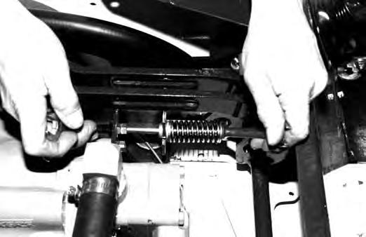
Remove the orifice and spring from the base end lift cylinder part of the control valve [B]
Loosen and remove the anti–cavitation valve [C].
Using a magnet remove the ball [D]
HYDRAULIC CONTROL VALVE (Gresen) (Cont’d)
Lift Section (Cont’d)
Using a wire hooked on the end remove the ball seat[A]
A
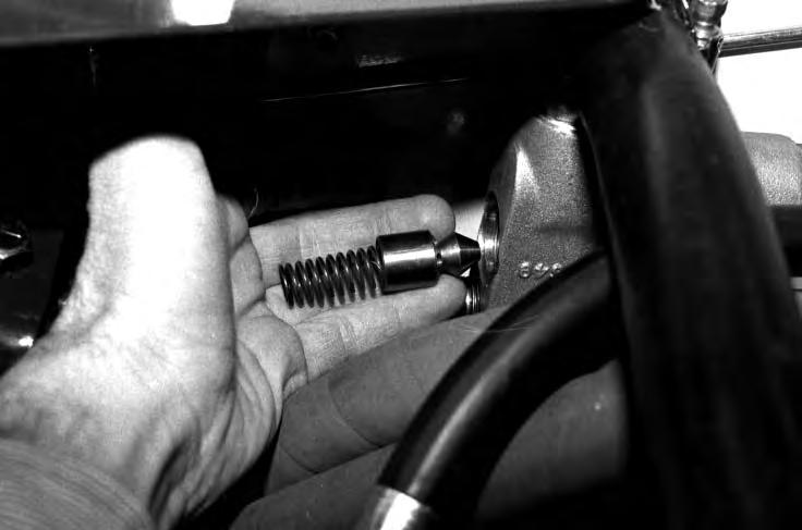
Using a magnet remove the spring and poppet frominside the lift section.
Remove and discard the O–ring from the anti–cavitation valve [B]
B
Check the anti–cavitation parts for wear [C]
Put grease in the anti–cavitation seat. Install the ball on the seat [D]
HYDRAULIC CONTROL VALVE (Gresen) (Cont’d)
Lift Section (Cont’d)
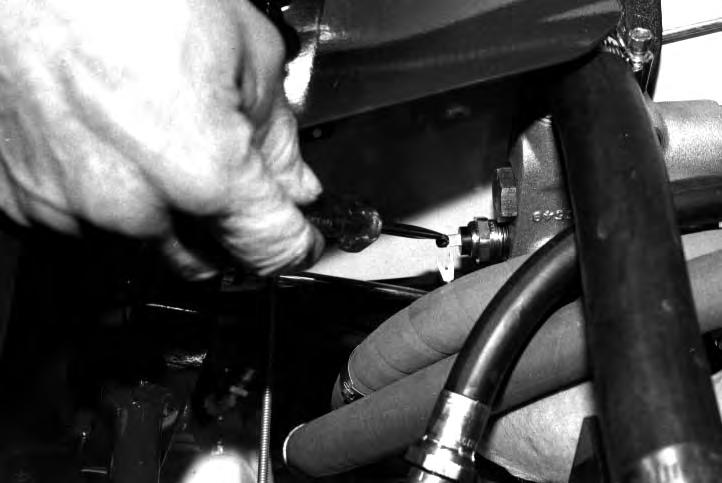
Remove the port relief valve [A].
Remove and discard the O–rings from the port relief valve [B]
Lubricate and install new O–rings on the port relief valve. Install the port relief valve into the lift section.
Remove the cap screws and remove the cap [C]
The detent assembly has small springs and balls. Do not lose these parts during disassembly and assembly.
Remove the valve spool from the lift section [D].
NOTE:DO NOT remove the spool bolt from the valve spool unless the spring is broken. If the bolt is to be removed see Page 2–17 for the correct procedure.
HYDRAULIC CONTROL VALVE (Gresen) (Cont’d)
Lift Section (Cont’d)
Remove and discard the O–ring from thevalve spool [A].
A
Remove the screws from the seal plate. Remove the seal plate and the retainer washer [B]
Remove the back–up washer and the O–ring [C]
C
Auxiliary Section
Remove the load check from the auxiliary section [D]
HYDRAULIC CONTROL VALVE (Gresen) (Cont’d)
Auxiliary Section (Cont’d)
Remove the screws holding the detent cap in position[A]
A
Remove the spool from the valve section [B]
Remove the screws, remove the seal plate and the retainer washer [C].
Installation: ALWAYS use new O–rings on the valve spool.
Remove the back–up washer and the O–ring [D].
HYDRAULIC CONTROL VALVE (Gresen) (Cont’d)
Valve Spool Bolt
NOTE:DO NOT remove the spool bolt from the spool unless the spring is broken.
The spool bolt is held tightly by LOCTITE. Failure to apply heat to the spool will result in the spool bolt breaking. I–2127–0597
Put the yoke end of the spool in a vise and remove the spool bolt [A]
Apply heat to the spool bolt for removal.
Installation: Apply LOCTITE to the spool bolt and tighten the bolt to 60–96 in.–lbs. (6,8–10,8 Nm) torque.
Adjusting The Auxiliary Detent
The tool listed will be needed to do the following procedure:
MEL1191 – Drag Link Socket
Remove the detent cap screws and remove the detent cap [B]
Use the tool listed to loosen the cap screws [C]
Remove the cap from the vise.
Check the spring. Check that there are twelve balls and that they are not damaged.
If there is any damage replace the complete detent assembly.
Install the cap back on the control valve and tighten the screws.
Turning the adjustment screw IN will increase the force it takes to move the auxiliary lever.
Turning the adjustment screw OUT will increase the force it takes to move the auxiliary lever.
HYDRAULIC PUMP (S/N 14999 & Below)
Checking The Output Of The Hydraulic Pump
The tools listed will be needed to do the following procedure:
OEM1238 – Hydraulic Tester
MEL10006 – Flowmeter Fitting Kit
MEL1138A – Remote Start Switch
Wear safety glasses to prevent eye injury when any of the following conditions exist:
• When fluids are under pressure.
• Flying debris or loose material is present.
• Engine is running.
• Tools are being used.
W–2019–1285
Do not turn the flow control valve (on tester) all the way off. If you do, there will not be a relief valve in the system.
I–2025–0284
NOTE:Make sure that all air is removed from the system before beginning the test. Air in the system can give an inaccurate test.
Lift and block the loader. (See PREVENTIVE MAINTENANCE Section 1 for the correct procedure.)
Connect the remote start switch. (See PREVENTIVE MAINTENANCE Section 1 for the correct procedure.)
Disconnect the hose at the outlet of the hydraulic pump [A]
Connect the inlet of the tester to the outlet of thehydraulic pump.
Connect the outlet of the tester to the hose disconnected from the hydraulic pump.
NOTE:Make sure that the restrictor valve on the tester is fully open.
HYDRAULIC PUMP (S/N 14999 & Below)
Checking The Output Of The Hydraulic Pump (Cont’d)
Start the engine and run at low RPM.
If no flow is indicated on the tester, the hoses are connected wrong. Increase the engine speed to full RPM*.
Warm the hydraulic fluid to 140 °F (60°C) by turning the restrictor knob on the tester to about 1000 PSI (6895 kPa). DO NOT exceed system relief pressure [A].
Open the restrictor and record the free flow (GPM) at full RPM.
Activate the auxiliary hydraulics (right steering lever) into the detent position. Record the highest pressure (PSI) and flow (GPM) at full RPM.
The high pressure flow must be at lest 80% of free flow.
HIGH PRESSURE FLOW (GPM)
% = X 100
FREE FLOW (GPM)
A low percentage may indicate a failedhydraulic pump or it may be caused by air in the system. Make sure that all the air is removed from the system.
Removal And Installation
When repairing hydrostatic and hydraulic systems, clean the work area before disassembly and keep all parts clean. Always use caps and plugs on hoses, tubelines and ports to keep dirt out. Dirt can quickly damage the system.
I–2003–0888
*See the SPECIFICATIONS Section 8 for system relief pressure and full RPM. The system relief pressure must be per specification before the test is run.
HYDRAULIC PUMP (S/N 14999 & Below) (Cont’d)
Removal And Installation (Cont’d)
Drain the hydraulic/hydrostatic reservoir. (See Page 2–34.)
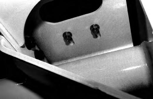
Remove the hydraulic hoses and tubelines from the port block [A]
Remove the small mounting bolt (Item 1)[A] at the top of the port block.
Remove the large bolt at the top of the port block [B]
Remove the port block.
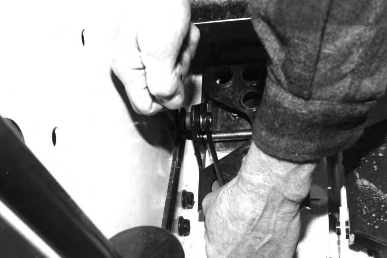
Remove the nuts from the pump mounting bolts [C].
Installation: Tighten the bolts to 40–50 ft.–lbs. (55–67 Nm) torque.
Remove the outlet hose from the hydraulic pump [D]
HYDRAULIC PUMP (S/N 14999 & Below) (Cont’d)
Removal And Installation (Cont’d)
Remove the pump bracket bolt [A].
Installation: Tighten the bolts to 65–70 ft.–lbs. (89–94 Nm) torque.
A
Remove the steering linkage and adjustment bolt [B]
Raise the pump a small amount and move the pump mount forward [C]
D
HYDRAULIC PUMP (S/N 14999 & Below) (Cont’d)
Removal And Installation (Cont’d)
Remove the inside steering linkage bar [A].
Remove the hydraulic pump mounting bolts [B]
Installation: Tighten the bolts to 65–70 ft.–lbs. (89–94 Nm) torque.
Remove the hydraulic pump [C]
HYDRAULIC PUMP (S/N 15001 & Above) Removal And Installation
When repairing hydrostatic and hydraulic systems, clean the work area before disassembly and keep all parts clean. Always use caps and plugs on hoses, tubelines and ports to keep dirt out. Dirt can quickly damage the system.
Drain the hydraulic/hydrostatic reservoir. (See Page 2–34.)
Remove the inlet hose at the top of the hydraulic pump [A]
Remove the nuts at the pump mounting bolts [B].
Installation: Tighten the bolts to 4–50 ft.–lbs. (55–67 Nm) torque.
Remove the outlet hose from the hydraulic pump [C]
Remove the pump mounting bracket bolts [D].
Installation: Tighten the bolts to 65–70 ft.–lbs. (89–94 Nm) torque.
HYDRAULIC PUMP (S/N 15001 & Above) (Cont’d)
Removal And Installation (Cont’d)
Remove the steering linkage and adjustment bolt [A]
Raise small
HYDRAULIC PUMP (S/N 15001 & Above) (Cont’d)
Removal And Installation (Cont’d)
Remove the hydraulic pump mounting bolts [A].
Installation: Tighten the bolts to 65–70 ft.–lbs. (98–94 Nm) torque.
Remove the hydraulic pump [B].
Vane Pump Drive Shaft Removal And Checking
Remove the snap ring [C]
Remove the coupler [D]
HYDRAULIC PUMP (S/N 15001 & Above) (Cont’d)
Vane Pump Drive Shaft Removal And Checking (Cont’d)
Remove the shaft [A]
Check the shaft for damage and wear [B]
Hydraulic Pump Starting Procedure
Check the hydraulic/hydrostatic reservoir and add oil as needed. (See SPECIFICATIONS for the correct oil.)
Put jackstands under the front axles and rear corners of the frame before running the engine for service. Failure to use jackstands can allow the machine to fall or move and cause injury or death.
W–2017–0286
Start the engine and run at half throttle for several minutes.
Operate the hydraulic control valve at 3 second intervals for several minutes to build up pressure. Increase engine speed to full throttle.
Operate the hydraulic control valve again for several minutes.
Slow the engine and check for leaks. Check the reservoir and add oil as needed. Remove the jackstands.
PORT BLOCK (S/N 14999 & Below)
40 Micron Filter (Bronze)
The tool listed will be needed to do the following procedure:
MEL1177 – Filter Removal Tool
Replace the bronze (40 micron) filter every 500 hours of loader operation.
When repairing hydrostatic and hydraulic systems, clean the work area before disassembly and keep all parts clean. Always use caps and plugs on hoses, tubelines and ports to keep dirt out. Dirt can quickly damage the system.
Stop the engine and raise the operator cab.
Drain the hydraulic reservoir. (See Page 2–34.)
Remove the center hose at the port block [A]
Remove the fitting from the port block [B].
Install the filter removal tool on the filter [C].
Remove the filter and sleeve from the port block [D]
PORT BLOCK (S/N 14999 & Below) (Cont’d)
40 Micron Filter (Bronze) (Cont’d)
Remove the tool from the filter [A].
NOTE:DO NOT remove the sleeve before removing the bronze filter. Particles trapped by the filter may drop into the port block and enter the system. Always check the port block for debris and clean the bore.
Clean the filter and sleeve in solvent, use air pressure to dry them.
Install the spring, filter and sleeve on the tool [A]
Install the assembly into the port block [B]
Remove the tool, install the fitting and connect the hose.
Cold Weather By–Pass Valve
Stop the engine. Drain the hydraulic reservoir. (See Page 2–34.)
Raise the operator cab.
Remove the hose fitting on the port block [C]
Remove the spring from the port block [D].
PORT BLOCK (S/N 14999 & Below) (Cont’d)
Cold Weather By–Pass Valve (Cont’d)
Remove the poppet from the port block [A].
Clean the valve and check the valve seat in the port block. Replace the parts as needed.
NOTE:Always use new O–ring when assembling the port block.
Install the fitting in the port block and tighten.
Install the hose and fill the reservoir with hydraulic fluid.
Start the engine and run for several minutes.
Stop the engine. Check the reservoir and add oil as needed.
Neutral By–Pass Valve
Stop the engine and raise the operator cab.
Remove the hose and fitting from the port block [B].
A
Remove the by–pass valve from the port block [C]
Clean the valve. Check the seat in the port block. Replace the parts as needed.
Install the by–pass valve in the port block.
Install the hoses and fill the reservoir with hydraulic fluid.
Start the engine and run for several minutes.
Stop the engine. Check the reservoir and add fluid as needed.
PORT BLOCK (S/N 14999 & Below) (Cont’d)
Removal And Installation
Stop the engine and drain the hydraulic reservoir. (See Page 2–34.)
Raise the operator cab. (See PREVENTIVE MAINTENANCE Section 1.)
Remove the hoses and tubelines from the port block [A]
Remove the small bolt (Item 1) [A] from the port block.
Installation: Tighten the bolt to 25–28 ft.–lbs. (34–38 Nm) torque.
Remove the large screw at the top of the port block [B]
Remove the port block.
Clean all parts in solvent. Use air pressure to dry them.
PORT BLOCK (S/N 15001 & Above)
Cold Weather By–Pass Valve Removal And Installation
Stop the engine. Raise the operator cab. (See PREVENTIVE MAINTENANCE Section 1.)
Drain the hydraulic reservoir. (See Page 2–34.)
Remove the hoses and tubelines from the tee fitting at the port block [A]
Remove the tee fitting and the elbow from the port block [B].
Remove the poppet and spring from the port block [C]
Clean the valve in solvent and check the seat in the elbow fitting.
Replace the parts as needed.
Case Drain Relief Valve Removal And Installation
Stop the engine and raise the operator cab.
Drain the hydraulic reservoir. (See HYDRAULIC SYSTEM Section 3.)
Remove the plug from the port block [D]
PORT BLOCK (S/N 15001 & Above) (Cont’d)
Case Drain Relief Valve Removal And Installation (Cont’d)
Remove the spring and poppet, use magnet if needed [A].
Clean the valve with solvent. Check the valve seat in the port block. Replace the parts as needed.
A
Removal And Installation
Stop the engine and raise the operator cab. (See PREVENTIVE MAINTENANCE Section 1.)
Drain the hydraulic reservoir. (See Page 2–34.)
Remove the tubeline that goes to the cooler [B].
Remove the tee fitting from the port block with case drain hoses that come from the hydrostatic motors.
Remove the hose which comes from the hydraulic reservoir [C].
Disconnect the wire from the sender switch [D]
PORT BLOCK (S/N 15001 & Above) (Cont’d)
Removal And Installation (Cont’d)
Loosen the clamp on the hose which goes to the hydraulic pump.
Remove the port block mounting nut [A]
Remove the port block by moving it up and backwards. At the same time disconnect the large hose (Item 1) [A]
HYDRAULIC/HYDROSTATIC RESERVOIR
Use only recommended oil in the hydraulic system(Clark Bobcat fluid P/N 6563328 or 10W–30, 10W–40 Class SE motor oil). Use 5W–30 where temperatures are below –10°F (–23°C).
Checking And Adding Oil
Put the loader on a level surface.
The reservoir will be different according to the loader S/N’s.
Check the fluid level using the dipstick, pet cock or the sight gauge (Item 1) [A]
Add oil as needed [B].
Removing Hydraulic Oil
Remove the oil from the hydraulic reservoir and replace it with new oil every 1000 hours of operation. Also replace the oil after it has become dirty or after major repairs.
Remove the hydraulic filter element.
Remove the hose from the filter housing [C]
Drain the hydraulic fluid into a container [D]
HYDRAULIC/HYDROSTATIC RESERVOIR (Cont’d)
Removal And Installation
Raise the operator cab. (See PREVENTIVE MAINTENANCE Section 1.)
Remove the harness bracket [A]
Drain the hydraulic reservoir. (See Page 2–34.)
A
Remove the reservoir hose [B]
Remove the bolt holding the tank strap in position [C].
Remove the reservoir.
Installation: Install the reservoir with the strap and bolt. Install the reservoir hose and the harness bracket.
Fill the reservoir with the specified oil. (See Page 2–34.)
Lower the operator cab.
Start the engine and operate the hydraulic controls.Stop the engine and check for leaks.
Check the reservoir oil level and add oil as needed.
Oil Cooler
Removal And Installation (741)
Remove the grill.
Drain the hydraulic reservoir. (See Page 2–34.)
Remove the oil cooler mounting bolts [A]
Remove the tubelines from the oil cooler [B]
Remove the oil cooler [C].
Removal And Installation (742 & 743)
Remove the radiator as follows:
742 (See ENGINE SERVICE Section 7B.)
743 (See ENGINE SERVICE Section 7C.)
Remove the oil cooler from the radiator [D]
10 MICRON FILTER BY–PASS VALVE
Removal And Installation
Remove the hydraulic filter.
Remove the hoses and tubelines from the filter head.
Remove the filter head [A]
Put the filter head in a vise. Remove the cap, spring and poppet [B]
Check the poppet and the seating area for damage. Replace the parts as needed.
NOTE:Always use new O–rings when installing the by–pass valve.
HYDRAULIC CONTROL PEDALS (S/N 14999 & Below)
Removal And Installation
Disconnect the linkage at the pedal [A].
Remove the hair pins at the pivot pins [B]
Remove the pedal from the bracket.
Remove the bushing from the pedal, using a vise, install the new bushing in the pedal [C].
Adjustment
Loosen the nuts at the mounting bracket [D]
Slide the mounting bracket backward or forward until there is about 1–1/2 inches (38 mm) under the rear edge of the pedal.
Tighten the nuts to 25–28 ft.–lbs. (34–38 Nm) torque.
HYDRAULIC CONTROL PEDALS (S/N 15001 & Above)
Removal And Installation
Remove the bolt and nut at the linkage [A]
Check the rubber bushing in the pedal for wear and replace as needed.
Remove the two pedal mounting nuts (Item 1) [B] below the mounting plate.
Remove the pedal from the loader [C]
Adjustment
After installing the pedal, adjust the pedal so that there is clearance under the rear of the pedal so the valve spool will travel full stroke without the pedal hitting.
If the linkage bar is to be removed, disconnectit from the valve, the foot pedal and the pedal lock.
Slide the linkage bar toward the rear of the loader to remove.
Pedal Lock Linkage
Installation
If the pedal interlock linkage was removed, use the following procedure to install the linkage.
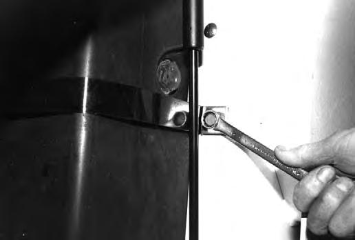
Install the bolts (Item 1) [A] from the outside the fender.
Install the plastic washer (Item 2) [A].
Install the interlock (Item 3) [A].
Install the plastic washer (Item 4) [A].
Put LOCTITE #242 on the threads of the bolts.
Install the special nuts (Item 5)[A]. make sure the special nut goes tight against the fender and that the plastic washer (Item 2 & 4) [A] go over the shoulder of the the special nut.
Tighten the special nut to 25 ft.–lbs. (34 Nm) torque.
AVOID INJURY OR DEATH
Adjust locking tabs on pedal control linkageso that lift and tilt control pedals are locked in neutral when the seat bar is up.
Adjustment
Check that the pedal interlock linkage is free and locks the pedals when returned to neutral position.
Check that the tab goes into the slot at the interlock [B].
If not, loosen the bolts (Item 1) [B] and adjust the tab for engagement.
Installation: Tighten the bolts to 25 ft.–lbs. (34Nm) torque.
TIGHTEN ALL HARDWARE PER SIZE TO GRADE 5 TORQUE (SEE STANDARD TORQUE SPECIFICATIONS FOR BOLTS, SECTION 9) UNLESS OTHERWISE SPECIFIED.