19 minute read
TROUBLESHOOTING Chart


The following troubleshooting chart is provided for assistance in locatingand correcting problems which are most common. Many of the recommended procedures must be done by authorized Bobcat Service Personnel only.
Problem
Engine will not turn over with the starter.
Engine will not start or is difficult to start.
Engine misses, runs irregularly or stops.
Engine overheats.
To much engine vibration.
Key To Correct The Cause
1.Battery has lost its charge.
2.Loose battery connections.
3.Loose starter connections.
4.Damaged starter switch.
5.Broken or damaged wire harness.
6.Damaged starter or solenoid.
7.Wrong starting procedure.
8.No fuel in tank.
9.Air cleaner is dirty.
10.Fuel vent in cap has restricted.
11.Damaged fuel lift pump.
12.Hydraulic/Hydrostatic load on engine.
13.Damage to fuel injection system
14.Excess fuel function not working.
15.Incorrect crankcase oil.
16.Dirty fuel, or fuel filter restricted or vent.
18.Poor compression.
19.Water in the fuel
20.Engine is overloaded.
21.Dirty engine cooling fins.
22.Engine has been operated with covers removed.
23.Dirty engine oil.
24.Exhaust system has restriction.
25.Loose engine mounts.
26.Worn rubber mounts.
Fuel System
Fuel System Service
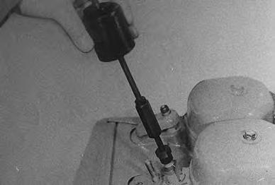
Engage the parking brake and start the engine. Push the throttle forward until it is against the stop.
If it is not against the stop loosen the nut (Item 1) [A], remove the pin (Item 2) [A] and turn the clevis to adjust throttle against the stop. High idle must be 2950–3000 RPM. If not correct, turn the adjustment screw.
Push down the solenoid rod (Item 1)[B] to check that the rod contacts fuel excess button. The lever must not hit the collar around the fuel excess button.
Adjust the lever until there is .0312 inch (0,79 mm) clearance [B]
NOTE:It is important that the linkage is adjusted so the plunger in the solenoid is in a full down position when engaged. If it is not, there will be damage to the solenoid.
Venting Air From The Fuel System
air must be vented from the fuel system after the following conditions.
Replacement of fuel filters.
Replacement of fuel system parts.
The machine has run out of fuel.
The fuel line has been replaced or repaired.
Removing water from the water trap.
To vent air from the fuel system use the following procedure:
Fill the tank with clean approved fuel.
Check the in–line filter and fuel line for dirt. both must be clean and have no restrictions.
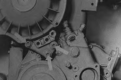
Loosen the slotted plug (Item 3) [A]
Move priming lever (Item 1) [C] until you cannot see air coming from the slotted plug (item 3) [A]. Tighten the fitting.
Repair Kit
(See Parts Fiche)
Repair Kit
(See Parts Fiche)
FUEL SYSTEM (Cont’d)
Venting Air From The Fuel System (Cont’d)
Loosen the injector fittings [A].
Turn the engine with the starter until no air bubbles come from the loose fitting.
Tighten the fittings.
NOTE:DO NOT over tighten the fittings.
Always clean up spilled fuel or oil. Keep heat, flames, sparks or lighted tobacco away from fuel and oil. Failure to use care around combustibles can cause explosion or fire which can result in injury or death.
Fuel Filters
There are two fuel filters used in the fuel system.
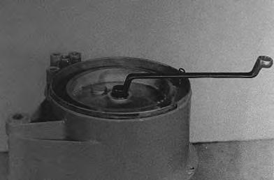
Fuel pump strainer [B].
To clean the fuel pump strainer remove the cover on the top of the pump. Strainer and gasket can be removedand cleaned with compressed air.
Filter element [C]
To install a new cartridge, loosen the bolt (Item 1) [C]
Remove the filter (Item 1) [D] and install the new filter.
NOTE:When the filters are removed or if the engine runs out of fuel, air enters the fuel system and venting of the fuel system is necessary.
a FUEL SYSTEMS (Cont’d)
Fuel Water Trap
The water is removed by loosening the screw (item 1)[A] at the bottom of the fuel filter. Tighten the screw after the water has been removed.
Fuel Lift Pump
Repair kits are available for the lift pump. Check the lift pump pressure by turning the engine over and checking with a gauge. If the pump does not give enough pressure, install the repair kit or replace the pump. (See Section 8 for the correct pressure.)
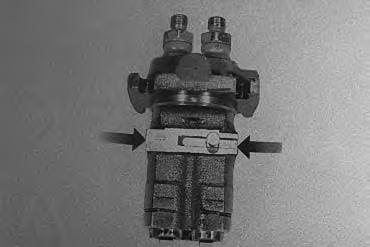
Fuel Injection Pump
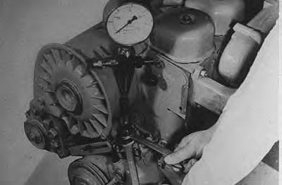
To check delivery valves and pump elements do the following:
Remove the fuel injection lines from the injection pump. Install the pressure indicator tool loosely to one of the open connections [B]. Turn the engine over several revolutions to remove air and ten tighten the nut.
Open the throttle.
Turn the engine with the starter until the pressure on the gauges is at least 1074 PSI (7909 kPa). Wait for one minute. The decrease in pressure must not be more than 145 PSI (100 kPa) on the delivery valve.
Turn the engine five revolutions. The pressure shown on the gauge must be at least 4347 PSI (300 bar).
If either of the two pressures are low the pump is damaged.
FUEL SYSTEM (Cont’d)
Injection Pump Removal And Installation
NOTE:The excess fuel button must not be engaged.
Disconnect the fuel injection lines and the fuel lift pump. Remove the inspection plug (Item 1)[A] at the front cover.
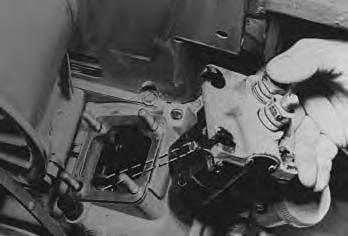
Remove the four nuts and remove the pump[B]. Note the number of shims (Item 1) [B] used under the pump.
Remove the screw and sleeve from the pump.
Installation: Tighten the screw to 2 ft–lbs. (2,5 Nm) torque.
Replace the injection pump if it is damaged or worn.
Put a new gasket on the pump fastening surface.
Turn the camshaft so the cam lobes cannot be seen.
Measure the distance from the top of the gasket to the camshaft [C]. Add shims on the top of the gasket until the distance is 3.252–3.256 inches (82,6–82,7 mm) [C]
FUEL SYSTEM (Cont’d)
Injection Pump Removal And Installation (Cont’d)
Align the ball on the pump rack [A].
Install the injection pump and connect the fuel line using new gaskets on both sides of the banjo fitting.
Install the screw and sleeve.
Install the plug in the front cover.
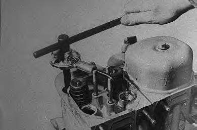
Use the following procedure to find top dead center (TDC): turn the pulley clockwise 45 °. Push down one of the valves on the #2 cylinder (closest to the pulley) with a screwdriver. Put a piece of 1/4 inch (5,6 mm) spacer between the valve stem and the rocker arm [B]
Check the valve clearance and adjust as needed. Both intake and exhaust valves. Clearance must be .006 inch (9,15 mm) cold.
Turn the pulley counterclockwise by hand so that the piston closest to the pulley, #2 cylinder, is at the point of maximum compression (TDC).
Carefully turn the pulley by hand, counterclockwise until the piston hits the valve.
Turn the pulley by hand at a slow rate. Be careful not to damage the valve or the piston.
I–2129–0697
Put a mark on the pulley in line withthe mark on the engine cover [C]. Turn the pulley clockwise about 45 ° and remove the spacer.
Turn the front pulley past (TDC) 90 ° counterclockwise. Put the 1/4 inch (5,5 mm) spacer in between the same valve stem and rocker. Carefully turn the pulley by hand, clockwise until the piston again hits the valve. Put a mark at this position [C]. Turn the pulley counterclockwise 45° and remove the spacer.
Install the cylinder head valve covers.
Use a steel flexible rule to mark and measure the half–way position between the two marks [D]. This is (TDC), top dead center.
NOTE:When the center mark on the pulley is in line with the mark on the housing #2 cylinder is (TDC).
The excess fuel button must be in the UP position.
Make a mark 25 ° before TDC. this mark is 1.4 inches (35,6 mm) counterclockwise of the TDC mark [A]
Install the capillary tube (tool P/N 003–1085) in the injection pump fitting for the #2 cylinder [B]
NOTE:If the capillary tube is not available the clear plastic cartridge from a ball point pen can be installed in the hole of the pump connection.
Vent the air from the fuel system by turning the engine several revolutions with the starter until there is no air coming up with the fuel.
Turn the engine by hand in the directionof normal rotation at a slow rate until fuel begins to show in the clear tube. When this happens the 25 ° mark on the housing is in alignment [C]
If it is not in alignment, loosen the injection pump and move it in or out for adjustment of the injection timing[D].
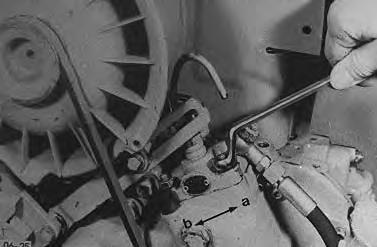
Direction A – Advanced Timing.
Direction B – Retarded Timing.
FUEL SYSTEM (Cont’d) Fuel Delivery Adjustment
Engage the parking brake.
Start the engine and run at full RPM.
Push the levers forward at a slow rate until the engine begins to stall. There must be very little smoke coming from the muffler.
NOTE:Be sure button (Item 1) [A] is up.
Incorrect adjustment of the fuel delivery will shorten the life of the engine. At high altitudes, the engine will have a rich mixture if the fuel delivery adjustment is not correct. This will damage the engine.
I–2131–0697
If there is excessive black smoke put the levers in neutral position. Remove the cap and copper washer from the fuel adjustment screw. Turn the screw in or out untilthere is a small amount of black smoke coming from the muffler. Tighten the lock nut on the screw [A]
Install the washer and the cap.
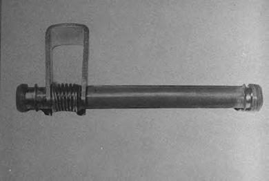
Fuel Injection Nozzles
Removal And Installation disconnect the fuel lines.
Remove the nut and the yoke [A]
Remove the nozzle. Use a nozzle puller if necessary (P/N 003–0463 extractor and 003–0536 slide hammer) [B]
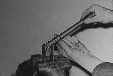
Injection Disassembly And Repair (In The Shop)
The tools listed will be needed to do the following procedure:
OEM1064 – Diesel Fuel Injection Nozzle Tester
OEM1065 – Accessory Kit
Special equipment is needed for service of injection nozzles. The following procedures are given only for cleaning and inspection.
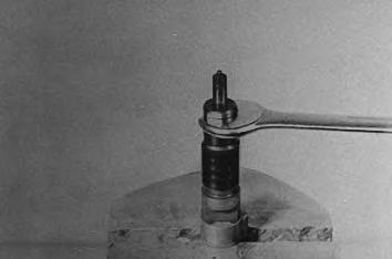
Clamp the body of the injector valve in a vise. Remove the lower parts and the internal parts vary carefully [C].
Wash them in a clean diesel fuel.
Use a stiff bristle brush (brass) to clean the injector tips.
DO NOT use a steel brush to clean the injector tips.
Check the needle valve and seat for wear and dirt. Replace both if either is damaged.
Assemble the injector. Check the release pressure and spray pattern with an injector tester. (See Section 8A for SPECIFICATIONS .)
NOTE:A new sealing gasket MUST be installed each time an injector is replaced.
Installation is the reverse of removal.
BLOWER FAN Removal And Installation
Be careful not to damage the fan blades. I–2133–0697
Remove the belt shield and loosen the alternator to remove the v–belt [A]
Remove the alternator bracket and the three bolts that hold the blower in position [B]. Remove the blower assembly.
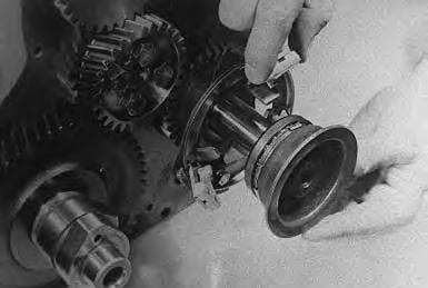
Disassembly And Assembly
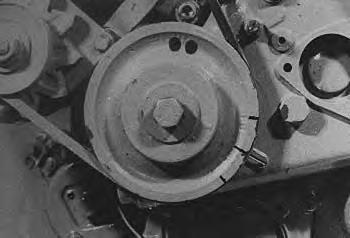
Clamp the pulley of the cooling fan in a vise withprotective aluminum jaws and remove the center bolt [C]
Remove the blower fan [D]
Remove the drive shaft from the fan housing using a soft metal drift punch.
Remove the ball bearing from the drive shaft using a bearing puller.
BLOWER FAN (Cont’d)
Disassembly And Assembly (Cont’d)
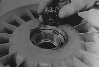
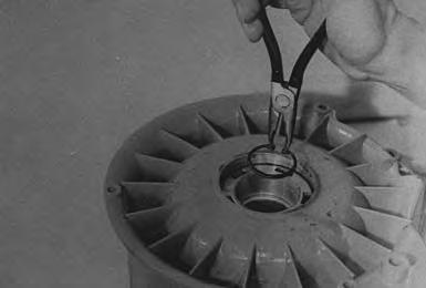
Remove the snap ring from theball bearing in the housing [A].
Remove the ball bearing using a shaft metal drift punch [B].
Fill the new bearing with high temperature bearing grease.
Press the small bearing into the fan housing with the closed side down.
Install the snap ring to hold the bearing in position.
Press the large ball bearing over the drive shaft with the closed side toward the v–belt pulley.
Press the fan shaft and bearing into the housing.
Clamp the cooling fan pulley in a vise.
NOTE:Do not damage the pulley.
Position the rotor wheel and tighten the bolt to 26 ft.–lbs. (35 Nm) torque.
Engine Service
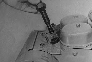
See Section 8A for the SPECIFICATIONS
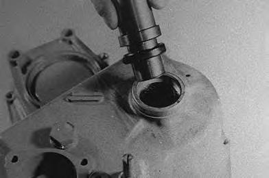
To check compression install compression tester in the injector opening [A]. Turn the engine four revolutions or until highest reading is obtained. Compression must be 340–412 PSI (23,5–28,5 bar).
Install a new bearing in the air blower each time the engine is overhauled.
Special bolts are used in many locations of the engine. These bolts are first tightened to 22 ft.–lbs. (30 Nm) torque. To correct torque. (See SPECIFICATIONS Section.)
When overhauling an engine always install new gasket, O–rings and seals.
Install the correct number of shims on each cylinder during assembly [B]
Engine Removal
To remove the engine use the following procedure:
Disconnect the negative battery cable first. Then disconnect the positive battery cable.
Disconnect the ground wire from the frame. Disconnect the wires from the solenoid [C].
Remove the grill [D].
ENGINE SERVICE (Cont’d)
Engine Removal (Cont’d)
Release the tie clamp holding the fuel line to the shield [A]
Remove the bolts holding the engine shield in position[B] & [C].
A B
B–04590
B–04589
ENGINE SERVICE (Cont’d)
Engine Removal (Cont’d)
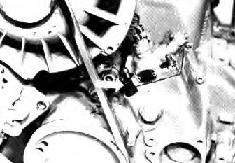
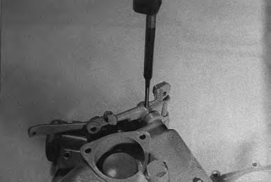
Disconnect the exhaust pipe [A]
Remove the throttle linkage bolt [B]
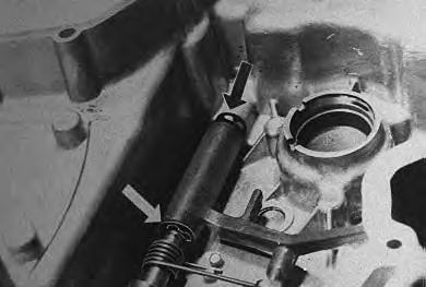
Remove the cotter key from the throttle pin [C]
Remove the throttle pin [D].
ENGINE SERVICE (Cont’d)
Engine Removal (Cont’d)
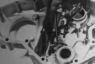
Remove the throttle linkage [A].
Disconnect the air cleaner hose [B]
Shut the fuel off at the fuel tank anddisconnect the return fuel line [C]
Disconnect the inlet fuel line [D]
ENGINE SERVICE (Cont’d)
Engine Removal (Cont’d)
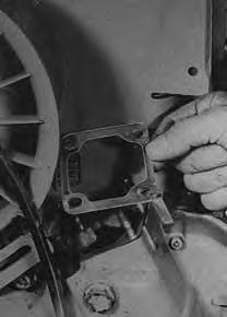
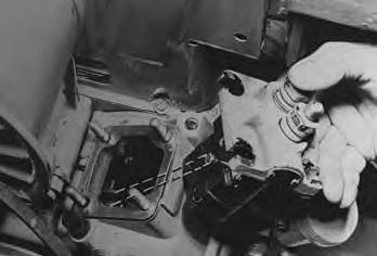
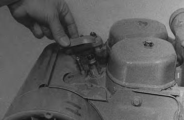
Remove the fuel filter head assembly [A].
Remove the bracket holding the engine harness connector and move the bracket and connector into the engine compartment [B]
Put jackstands under the front axles and rear corners of the frame before running the engine for service. Failure to use jackstands can allow the machine to fall or move and cause injury or death.
Put jackstands under the loader frame and front axles.
Remove the four bolts holding the engine mounts on the engine plate [C]
Remove the engine by lifting it a small amount and pulling carefully [D].
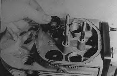
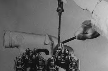
CYLINDER HEAD AND VALVES Removal
Remove the blower and air housing.
Remove the valve covers and the rocker arm bracket[A].
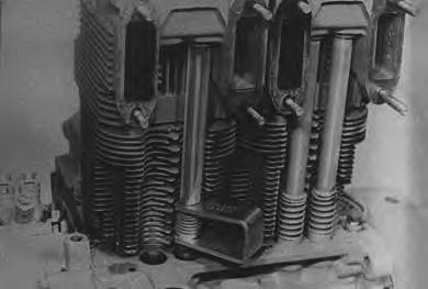
Remove the plugs and push rods [B].
Remove the four bolts that hold the head in position with a socket wrench. Loosen the bolts evenly [B]
Lift the cylinder head off the engine and remove the push rod cover tubes.
Disassembly And Assembly
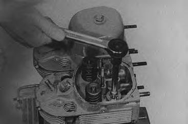
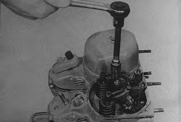
Use a valve spring compressor to remove the valves and springs [C]
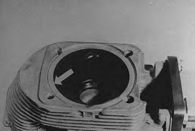
Check the head seating surface for damage [D]. Light scratches can be removed by grinding the head and the cylinder with fine grinding compound. Use tool P/N 003–0426 (available from you local Deutz dealer) when there is more damage.
CYLINDER HEAD AND VALVES (Cont’d)
Disassembly And Assembly (Cont’d)
Grind the old valves if you are going to use them again. Install the valve and measure the distance to the head. If the valve depth is over the maximum the valve seat will need to be replaced [A]
Use valve seat removal tool kit P/N 003–3409.
Heat the cylinder head to 450 °F (250°C) in an oven. Remove the head from the oven using insulated gloves. Tap out the valve guides from the bottom (Piston side) with a punch [B]
Install valve seat removal tool and remove the valve seat [C]
NOTE:The valve seat removal tool will need to be fabricated locally.
CYLINDER HEAD AND VALVES (Cont’d)
Disassembly And Assembly (Cont’d)
Check the cylinder head temperature. It must be 450 °F (250°C). Use a punch and hammer to install new guides [A]
NOTE:The snap ring on the guide must contact the head to be installed correctly.
Install a new valve seat in the bore and tap into position [B]. Use tool (P/N 003–3409 available from your local Deutz dealer).
NOTE:Never use too much force when installing valve guides and valve seats. The cylinder head must be heated to the correct temperature and there must not be anydebris (burrs).
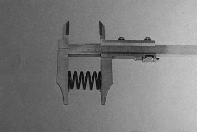
Measure the valve springs for correct length [C]. (See Section 8A for SPECIFICATIONS .)
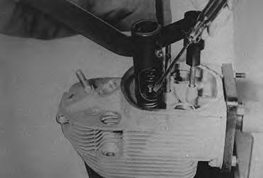
Apply lubricant (oil) to the valve stems and install the valve stems. Install the spring caps, springs and retainer with a spring compressor [D]
CYLINDER HEAD AND VALVES (Cont’d)
Disassembly And Assembly (Cont’d)
Remove the rocker arms from the bracket and check them for wear. Install new bushings if needed [A]
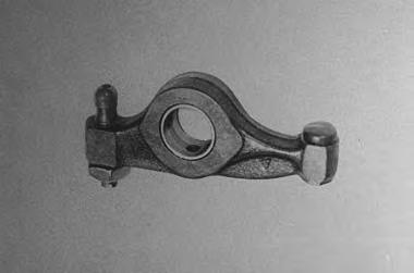
NOTE:The oil holes in the rocker arm and the busing must be aligned.
Checking Piston Crown Clearance
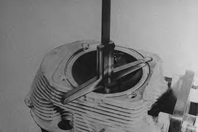
Position lead wire to solder, approximate diameter .060 inch across the piston as shown [B]
Use grease to hold the solder in position. The piston must be below TDC.
I–2134–0697
Cylinder Head Installation
Put he cylinder head on the engine cylinder and install the head bolts with the washers.
Tighten bolts to 22 ft.–lbs. (30 Nm) torque. Tighten all the head bolts to 30° with a degree scale tool (P/N 003–0500 available from you local Deutz dealer). Turn the engine one complete revolution (360°) [C].
Remove the cylinder head bolts and the cylinder head. Mark the cylinder heads to their cylinders.
Remove the lead wire and measure the thinnest points. If clearance is not within specifications add or remove shims between cylinder and crankcase. (See Piston Crown Clearance.)
NOTE:When installing head use this method to get correct clearance.
If there is not enough clearance remove the cylinder and put the needed number of shims below the liner.
If there is too much clearance remove the cylinder and remove the correct number of shims.
Use a thick shim instead of several thin ones.
Before installing the cylinder heads measure the cylinder head bolts for correct length. (See ENGINE SPECIFICATIONS .)
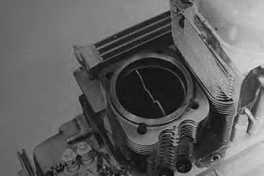
Hold a straight edge across the top of the heads [D] Move the cylinder heads until the two cylinder heads are in alignment.
CYLINDER HEAD AND VALVES (Cont’d)
Cylinder Head Installation (Cont’d)
Tighten the head bolts. Use tool P/N 003–0500 (available from you local Deutz dealer) to get the correct angle for tightening. (See Section 8A for SPECIFICATIONS ) [A].
CYLINDER HEAD AND VALVES (Cont’d)
Cylinder Head Installation (Cont’d)
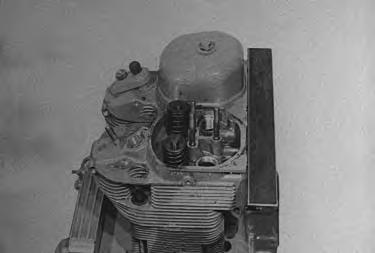
Install the push rods and the rocker arm bracket. Adjust the rocker arms as needed [A]
The rocker arms have an oilmeter screw [B]. One thread must be showing over the top of the nut. Check to see that there is small amount of oil flow toward the thrust pad.
Install all other parts removed during removal of the cylinder heads.
CYLINDER, PISTONS AND CONNECTING RODS
Disassembly And Assembly
NOTE:Cylinders may be removed with the piston and connecting rod in position it is best to remove and install the piston rod and cylinder together to prevent damage toparts.
Remove the cylinder head. (See Page 7A–13.)
Remove the oil pan.
Remove the bolts that hold the cap tothe connecting rod. Mark the bearings to the correct connecting rod if they are to be used again [A].
Lift out the cylinder, piston and rod together [B]
NOTE:Count the number of shims under the cylinder.
Remove the piston from the cylinder and remove the snap rings holding the piston wrist pins in position.
It may be necessary to heat the piston and to remove the piston wrist pin.
Remove the piston rings and clean the piston. Checkthe following for wear or damage.
Piston and ring grooves.
Piston wrist pin.
Connecting rod wrist pin bores [C]
CYLINDER, PISTONS AND CONNECTING RODS (Cont’d)
Disassembly And Assembly (Cont’d)
Check the rod bores for alignment [A]
Check the cylinder bore in several locations [B]
Use a press to remove the bushing from the rod if the bearing needs replacement [C]
Hone the cylinder and check the size ofthe cylinder. Use a piston to push the rings into the bore. check the end gap of the rings. (See Section 8A SPECIFICATIONS ) [D].
CYLINDER, PISTONS AND CONNECTING RODS (Cont’d)
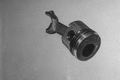
Disassembly And Assembly (Cont’d)
The arrow at the top of the piston must be pointed toward the long side of the piston rod [A]
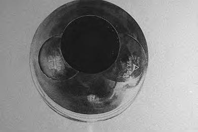
Assemble the piston, install the piston wrist pin through the rod and the piston and install the snap rings.
Install the piston rings on the piston with the mark on the ring toward the top. Turn the piston rings so the gaps are 120° apart.
Install the piston assembly in the cylinder with the arrow on the top of the piston, pointing toward the exhaust side of the engine [B]. Use ring compressor tool P/N 003–0430 (available from your local Deutz dealer).
If the old bearings are to be used again, install them as marked.
If new bearings are to be installed, use plastic gauge to check the clearance of the bearing to the crankshaft. (See Section 8A SPECIFICATIONS .)
Install the shims on the cylinder as noted during disassembly.
Install the piston assembly in the cylinder (using the ring compressor) with the arrow on the top of the piston pointing toward the push rod (camshaft) side of the engine [D]
Be careful not to damage the crankshaft surface. Install and tighten the rod caps. (See Section 8A SPECIFICATIONS .)
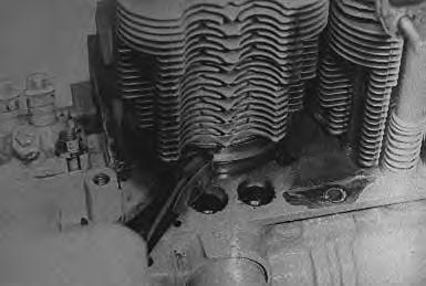
OIL PUMP, FILTER HOUSING AND RELIEF VALVE
Oil Pump Removal And Installation
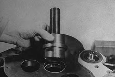
Remove the oil pan and the front cover. Remove the bolt that holds the oil pump in position [A]
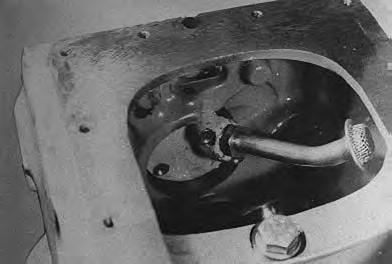
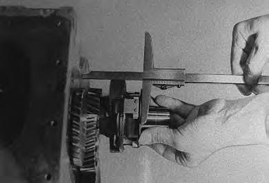
Turn the pump and remove it from the crankcase [B]
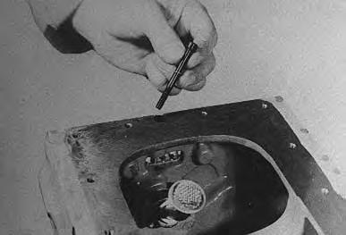
NOTE:The oil pump cannot be serviced. a new oil pump with a new gear must be installed if any part has damage. Check the end play to find the condition of the oil pump. (See Engine SPECIFICATIONS Section 8A.) [C].
Oil Pressure Relief Valve
The oil pressure relief valve is in the engine block. Do not change the length of the spring and do not add shims to the valve.
ENGINE FRONT COVER Removal
Remove the fuel injection pump. (See Page 7A–3.)
Remove the cooling blower, generator and pulley fromthe governor shaft.
Remove the cover bolts.
Remove the front cover. Be careful not to lose the dowel pins.
Disassembly And Assembly
Put new sealing washers under the two plugs [A]
Remove the old seal from the governor shaft [B]. Install
Check the excess fuel button for damage or wear. Replace the O–ring and put grease in the center groove for the O–ring [D]
ENGINE FRONT COVER (Cont’d)
Disassembly And Assembly (Cont’d)
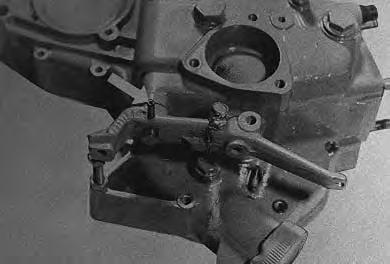
If you replace the spring on the fuel excess button, the spring must be turned 3/4 of a turn to put tension to the lever [A]
Remove the pin from the throttle control lever, and remove the lever from the shaft [B]
Remove the two bolts* which hold the governor spring in position. Remove the shaft.
* Later model engines have a spring with four bolts.
ENGINE FRONT COVER (Cont’d)
Disassembly And Assembly (Cont’d)
Put the spring on the control arm [A].
ENGINE FRONT COVER (Cont’d)
Disassembly And Assembly (Cont’d)
Install the throttle lever and leaf spring on the shaft and install the locking pin [A]
Installation
Put dowel pins in front cover and apply gasket sealant to the front cover [B]
With the camshaft pushed against its contact surface measure the distance from the front of the collar to the front of the engine housing [C]
Measure the distance between the stop and the joint surface of the front cover [D].
Dimension B must be more than dimension A. If the distance is more than .024 inch (0,6 mm) the front cover must be replaced.
Install the cover bolts and tighten them evenly. Adjust high and low idle speeds. (See Section 8A SPECIFICATIONS .)
Governor
Removal And Disassembly
Remove the injection pump. (See Page 7A–2.)
Remove the blower and front cover. (See Page 7A–26.) Remove the governor shaft.
Use two screwdrivers to remove the gear and shaft from the engine block.
Remove the wire retainer and disassemble the governor. Check all parts for wear or damage.
Assembly and Installation
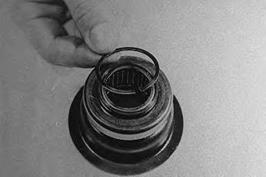
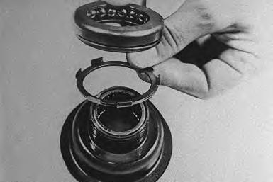
Put grease on the inside of the ring to hold the balls in position. Install the balls. Put the outer raceover the balls (insert) [A]
Turn the bearing cup (Item 1)[A] face down and install the shims (Item 2) [A] with the tabs up.
Put the bearing assembly over the cup and shims and install the snap ring [B]
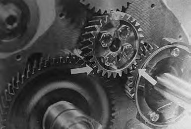
Use a shaft hammer to install the shaft and gear into the engine block. The timing marks must be in alignment.
Install the governor weights and the governor [D]. Install any other parts removed.
CAMSHAFT Removal And Installation
NOTE:Engine must be removed from the loader.
Remove the injection pump. (See Page 7A–1.)
Remove the blower and air housing, the front cover and the rocker arm covers. (See Page 7A–26.)
Remove the rocker arms and push rods.
Position the engine so the exhaust manifold is up.
Remove the fuel lift pump.
Remove the camshaft. Be careful not to damage the camshaft bushing.
Remove the oil pan. Remove the tappets.Check all parts for wear or damage.
If the bushing is good, it can be used again. If not, use a driver to push out the old bushing and install a new busing. Align the oil holes in the busing with hose in the block when you install a new bushing [A]
Install the tappets from inside the crankcase.
Put oil on the thrust washer and put it on the camshaft[B].
Install the oil pan and turn the engine upright.
Install the fuel lift pump, push rods and rocker arms.
Install the fuel injection pump and other parts removed.
Prime fuel injection system.
CRANKSHAFT
Removal
Remove the cylinder heads. (See Page 7A–13.)
Remove the pistons and rods. (See Page 7A–19.)
Remove the front cover. (See Page 7A–23.) Remove the crankshaft gear.
Remove the oil pan and the oil pump.
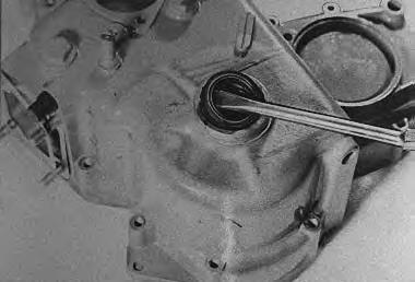
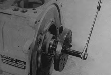
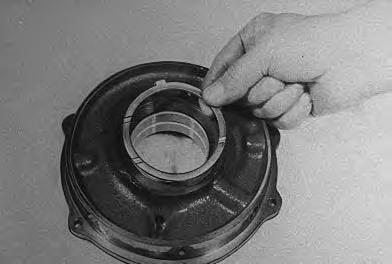
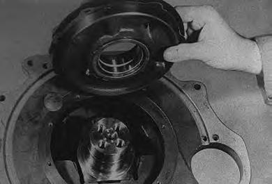
Remove the flywheel and end cover [A]
Remove the bolt from the center main bearing. Remove the crankshaft from the engine block.
Remove the center main bearing from the crankshaft[B]
Inspection
Clean all the parts and check them for wear or damage.
Replace the crankshaft or have it ground as needed. (See Section 8A for SPECIFICATIONS .)
Install the correct bearing shell in the center main bearing. Check the thrust washers for wear and damage. (See Section 8A for SPECIFICATIONS .)
Assembly
Install the correct bushing into the block and end plate. The oil holes in the bushings must be in alignment with the holes in the block and end plate [C]
NOTE:After installation the bearing must extend 0.055–0.067 inch (1,4–1,7 mm) outside the front of the block.
Put grease on the thrust washer in the crankcase to hold it in position. The tab on the washer must align with the slot [D].
CRANKSHAFT (Cont’d) Assembly (Cont’d)
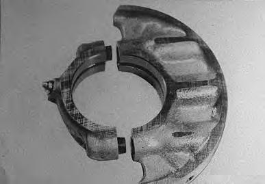
Install the bearings of the correct size in the center bearing support and install the support on the crankshaft. The numbers on the support must be matched [A].
The spray nozzle for cooling #1 piston must be turned toward the far side of the engine [A]
Put the crankshaft in the block. Be careful not to damage the bushing in the block during installation.
The hole in the bearing support must bein alignment with the holes in the block [B]
Install the thrust washer, seal and gasket in the end plate. When installing the shaft seal, make sure that the seal is pressed flush with the end plate edge [C]
The hole in the block must be in alignment with the hole in the plate. Put the plate in position and install the two bolts [D]
CRANKSHAFT (Cont’d) Assembly (Cont’d)
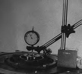
Measure the end play of the crankshaft [A]
If not in the specifications, install or remove papergaskets as needed to get the correct clearance.
Tighten all bolts in the end plate and the bolt in the main bearing support.
Check the crankshaft. The gear must fit on the location pin in the crankshaft and the timing marks must be in alignment [B]