24 minute read
HYDROSTATIC SYSTEM INFORMATION


CHARGE
When repairing hydrostatic and hydraulic systems, clean the work area before disassembly and keep all parts clean. Always use caps and plugs on hoses, tubelines and ports to keep dirt out. Dirt can quickly damage the system.
I–2003–0888
High Pressure Relief/Replenishing Valve Function
The valves for forward movement are different from the valves for reverse travel.
The high pressure relief/replenishing valves for forward travel, also release very high pressure.
The functions of the replenishing valves are:
1.To give replacement fluid to the low pressure side of the hydrostatic circuit. Replacement fluid is needed because of normal internal leakage and the controlled flow to the oil cooler for cooling; Function 1 [A] and Function 1 [B].
2.To keep high pressure fluid out of the low pressure side of the hydrostatic circuitry; Function 2 [A] and Function 2 [B]
3.To release high pressure caused by moving forward with a heavy load on the loader, Function 3 [A]
FUNCTION 1
Valve Moves for Charge Oil Replacement
FUNCTION 2
Valve Stays on Seat to Hold High Pressure for Drive
FUNCTION 3
Valve Release Very High Pressure to Protect System
CHARGE OIL
Valve Moves for Charge Oil Replacement
FUNCTION 1
Valve Stays on Seat to Hold High Pressure for Drive
FUNCTION 2
Steering Levers
Removal And Installation
NOTE:Early production machines used 3–piece assembly. Current production machines use 1–piece shield which must be removed as a unit.
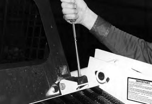
Remove the front panel [A]
When repairing hydrostatic and hydraulic systems, clean the work area before disassembly and keep all parts clean. Always use caps and plugs on hoses, tubelines and ports to keep dirt out. Dirt can quickly damage the system.
I–2003–0888
Remove the bolts and remove both side shields [B].
Remove the bolts from the steering lever shield[C] & [D].
STEERING LEVERS (Cont’d)
Removal And Installation (Cont’d)
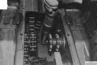
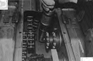
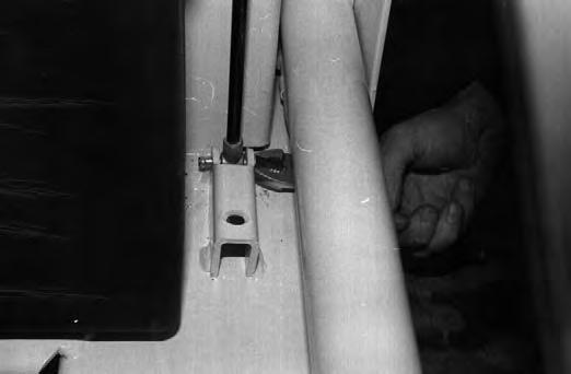
Remove the steering linkage at the steering levers [A].
Disconnect the auxiliary linkage from the right steering lever [B]
Remove the bolts (Item 1) [C] from the pivot bearings.
Installation: Tighten the bolts to 25–28 ft.–lbs. (34–38 Nm) torque.
STEERING LEVERS (Cont’d)
Repairing The Steering Levers
Remove the rubber bushing and the Teflon bushing from the steering levers.
Install the new rubber bushings into the steering levers using two sockets and a vise [A]
Install the Teflon bushings on the steering levers [B]
Install the two steering lever assemblies together [C].
Check the pivot bearings and replace as needed.
STEERING LINKAGE Adjustment
Put jackstands under the front axles and rear corners of the frame before running the engine for service. Failure to use jackstands can allow the machine to fall or move and cause injury or death.
W–2017–0286
Raise the operator cab. (See PREVENTIVE MAINTENANCE Section 1.)
Loosen the linkage (Item 1) [A] at both pintle arms.
Loosen the pintle bar bolts (item 2) [A]
Connect the remote start switch MEL1128A. (See PREVENTIVE MAINTENANCE Section 1.)
Start the engine and run at slow RPM.
Move the left steering lever until the tires do not turn (neutral). Adjust the rear pintle bar so that the bar is tight against both cams (Item 3) [A] of the pintle lever and the transmission is still in neutral.
Tighten the pintle bar bolts to 28 ft.–lbs. (38 Nm) torque.
Move the left steering lever backward and forward and let the transmission return to neutral. If the transmission does not go back to neutral. repeat the procedure.
STEERING LINKAGE (Cont’d)
Adjustment (Cont’d)
Move the right steering lever until the tires do not turn (neutral). Adjust the front pintle bar so that the bar is tight against both cams (Item 1) [A]
Tighten the pintle bar bolts to 28 ft.–lbs. (38 Nm) torque.
Move the right steering lever backward and forward and let the transmission return to neutral. If the transmission does not go back to neutral, repeat the procedure.
Tighten the bolts holding the steering linkage to the pintle levers to 12 ft.–lbs. (16 Nm) torque.
Install the locknuts on each bolt and tighten to 23 ft.–lbs. (31 Nm) torque.
Removal And Installation
Raise the operator cab. (See PREVENTIVE MAINTENANCE Section 1.)
Remove the steering linkage bolts from the steering levers [B]
Remove the bolts from the pintle arms [C]
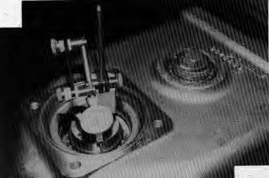
Remove the centering bolt and spring (Item 2) [A]
Installation: Adjust the centering spring bolt to compress the spring to 2.700 inches (68,6 mm) [A]
STEERING LINKAGE (Cont’d)
Removal And Installation (Cont’d)
Remove the centering bar (Item 1) [A].
Loosen the bolts (Item 2) [A] on the pintle levers (Item 3) [A]. Remove the pintle lever key (Item 4) [A]
Repairing The Pintle Lever
Remove the bolt at the lobes on the pintle lever [B].
Remove the rubber bushings from the pintle levers.
STEERING LINKAGE (Cont’d)
Repairing The Pintle Lever (Cont’d)
Install the new lobes on the pintle lever and tighten to 25–28 ft.–lbs. (34–38 Nm) torque [A]
Install the bushing and the guide in the pintle lever. Install the key on the shaft of the hydrostatic pump and install the pintle lever assembly [B]
Tighten the bolt on the pintle lever to 18–20 ft.–lbs. (24–27 Nm) torque [C]
HYDROSTATIC MOTOR Removal
When repairing hydrostatic and hydraulic systems, clean the work area before disassembly and keep all parts clean. Always use caps and plugs on hoses, tubelines and ports to keep dirt out. Dirt can quickly damage the system.
I–2003–0888
Remove the motor cover [A].
Remove the hoses from the hydrostatic motor. Note the location of the hoses for correct assembly [B]
Remove the mounting bolts and remove the motor [C]
NOTE:Refer to the Component Repair Manual for the disassembly and assembly procedure.
Installation: Tighten the mounting bolts to 65–70 ft.–lbs. (88–95 Nm) torque.
Hydrostatic Pump
When repairing hydrostatic and hydraulic systems, clean the work area before disassembly and keep all parts clean. Always use caps and plugs on hoses, tubelines and ports to keep dirt out. Dirt can quickly damage the system.
I–2003–0888
Checking The High Pressure Relief Replenishing Valves
The tool listed will be needed to do the following procedure:
MEL1173 – Gauge Test Kit
Lift and block the loader. (See PREVENTIVE MAINTENANCE Section 1 for the correct procedure.)
Raise the operator cab. (See PREVENTIVE MAINTENANCE Section 1 for the correct procedure.)
If there is a loss of drive in one direction, to one side of the loader, use the following procedure to check the valves.
Remove both plugs and the replenishing valves that controls the direction of drive that was lost [A]
Switch the replenishing valves around. Install andtighten the plugs.
Connect the remote start switch MEL1138A. (See PREVENTIVE MAINTENANCE Section 1.)
Start the engine and check the drive.
If the loss of drive goes to the other side, the valve which controls that side of the loader must be replaced.
To Use The Special Tool Kit (MEL1173)
Put jackstands under the front axles and rear corners of the frame before running the engine for service. Failure to use jackstands can allow the machine to fall or move and cause injury or death.
W–2017–0286
HYDROSTATIC PUMP (Cont’d)
Checking The High Pressure Relief Replenishing Valves (Cont’d)
Remove the high pressure hydraulic hose from the pump port. Install the 10,000 PSI gauge (from the kit) in the port.
When an engine is running in an enclosed area, fresh air must be added to avoid concentration of exhaust fumes. If the engine is stationary, vent the exhaust outside. Exhaust fumes contain odorless, invisible gases which can kill without warning.
W–2050–1285
Connect the remote start switch MEL1138A. (See PREVENTIVE MAINTENANCE Section 1.)
Run the engine at idle RPM. Engage the drive lever a small amount. The pressure must reach 3500–4000 PSI (24133–27580 kPa. DO NOT exceed 4000 PSI (27580 kPa).
Replace the valves as needed.
Checking Charge Pressure (S/N 14999 & Below) the tools listed will be needed to do the following procedure:
MEL1163 – Test Kit
MEL1138A – Remote Start Switch
Raise the operator cab. (See PREVENTIVE MAINTENANCE Section 1.)
Remove the temperature sender from the port block [A].
Connect the gauge (from the kit) to the port block in the temperature sender port [B]
The pressure should read 140–170 PSI (965–1172 kPa).
NOTE:Refer to the Component Repair Manual for the disassembly and assembly procedure. Remove the gauges. Install the switch and connect the sender wire.
Checking Charge Pressure (S/N 15001 & Above)
The tools listed will be needed to do the following procedure:
MEL1173A – Test Kit
MEL1138A – Remote Start Switch
Raise the operator cab. (See PREVENTIVE MAINTENANCE Section 1.)
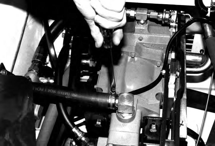
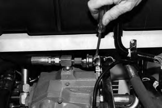
Remove the switch from the elbow on top of the hydrostatic pump.
Connect the gauge (from the kit) to the fitting as shown [C].
Connect the remote start switch MEL1138A. (See PREVENTIVE MAINTENANCE Section 1.)
Start the engine and run at full RPM.
The pressure should read 95–115 PSI (655–793 kPa).
NOTE:Refer to the Component Repair Manual for the disassembly and assembly procedure. Remove the gauges. Install the switch and connect the wire.
Diesel fuel or hydraulic fluid under pressure can penetrate skin or eyes, causing serious injury or death. Fluid leaks under pressure may not be visible. Use a piece of cardboard orwood to find leaks. Do not use your bare hand. Wear safety goggles. If fluid enters skin or eyes, get immediate medical attention from a physician familiar with this injury.
HYDROSTATIC PUMP (Cont’d)
Removal
Drain the hydraulic/hydrostatic reservoir. (See HYDRAULIC SYSTEM Section 2.)
Remove the front panel and side shields. (See Page 3–3.)
Remove the detent linkage [A].
Remove the steering linkage at the steering levers [B]
S/N 14999 & Below
Remove the hoses from the port block [C]
Disconnect the hose from the port block to the hydraulic/hydrostatic reservoir.
S/N 14999 & Below
S/N 15001 & Above
Remove the suction hose from the hydraulic pump [D]
Loosen the suction hose fitting at the port block.
Move the hose for ease of pump removal and installation.
S/N 15001 & Above
HYDROSTATIC PUMP (Cont’d)
Removal (Cont’d)
Remove the wires from the hydraulic temperature sender [A]
Remove the hydraulic filter hose (Item 1) [A]
Disconnect the high pressure hoses (Items 1 & 2) from the hydrostatic pump [B] & [C].
Disconnect the wire from the temperature switch on the port block.
HYDROSTATIC PUMP (Cont’d)
Removal (Cont’d)
NOTE:If the rear pump mount is to be removed make sure to note the location of the washers between the mount and frame. These washer(s) (Item 1) [A], must be installed at the correct location to give the pump and engine the correct alignment.
Remove the bolts from the rear hydrostatic pump mount. Move the pump forward and lift it up to remove it from the loader [B]. (Example shown is from S/N 14999 & Below.)
Remove the spline coupler from the input shaft on the rear of the pump.
NOTE:Refer to the Component Repair Manual for the Hydrostatic Pump Disassembly And Assembly.
Installation
Install the front pump mount using the same number of shims removed.
Lower the pump assembly into position on the transmission case and guide the spline pump drive shaft and coupler yoke into engagement.
Install the bolts in the front and rear pump mounts. Fasten the pump assembly to the rear mount.
Use key stock against the spider on the drive coupler to check alignment [C]
Loosen the engine mounts if necessary to align the drive coupler.
If the height alignment is not correct, add or subtract half thickness washers at the rear pump mount [D].
NOTE:Measure from engine mounting plate to center of pump shaft. Also measure engine distance to center of the flywheel, the two dimensions must be as close as possible.
Check engagement of coupling onto spline. Maximum clearance between pump drive flange and yoke is 1/4 inch (6,35 mm).
Tow Valves
The tool listed will be needed before attempting to tow the loader.
MEL1179–2 – Towing Tool
The loader can be moved (towed) for a short distance (at a slow speed) if it is unable to do so under its own power.
When repairing hydrostatic and hydraulic systems, clean the work area before disassembly and keep all parts clean. Always use caps and plugs on hoses, tubelines and ports to keep dirt out. Dirt can quickly damage the system.
Remove the high pressure relief plug. Remove the spring and the high pressure relief valve[A].
Remove the other plug.
Remove the other spring and the high pressure relief valve [B]
Install the owing tools (Items 1 & 2)[C] and then theplugs only.
NOTE:Remove the tow tools before trying to operate the loader.
TIGHTEN ALL HARDWARE PER SIZE TO GRADE 5 TORQUE (SEE STANDARD TORQUE SPECIFICATIONS FOR BOLTS, SECTION 9) UNLESS OTHERWISE SPECIFIED.
PARKING BRAKE Adjustment
When the brake is in good condition and adjusted correctly, it will keep the loader from moving when in the engaged position.
Loosen the nut (Item 1) [A] and turn the linkage rod to adjust the brake. There must be 1/4 inch (6,35 mm) free play under the rear edge of the pedal.
NOTE:If the correct adjustment cannot be reached by turning the linkage rod, the brake lever must be adjusted.
Remove the brake lever (Item 1) [B]
Turn the cam pin (Item 2) [B] counterclockwise until the brake pucks (Item 3) [B] make contact with the brake discs (Item 4) [B]
Put the brake linkage rod (Item 5)[B] into the brake lever. Install the linkage rod into the brake pedal.
When there is 1 inch (25,4 mm) of threads through the brake pedal install the brake lever on the cam pin. the brake pucks must still be making contact with the brake discs.
Install the lever (if so equipped) (Item 6)[B] and bolt (item 7) [B] on the cam pin and tighten to 65–70 ft.–lbs. (88–95 Nm) torque.
Install the spring (Item 8) [B]
Adjust the brake as described above.
PARKING BRAKE (Cont’d) Removal and Installation
Remove the seat assembly.
remove the control shields, steering levers and linkage. Remove the transmission covers and the brake block[A]
Installation: Align the brake discs so they are centered between the brake pucks.
Be careful not to damage the gasket when removing the transmission covers.
Remove the snap ring at the discs [B].
Remove the brake discs [C].
Check the brake discs for damage. Replace the discs as needed. Do not grind the discs.
PARKING BRAKE (Cont’d)
Block and Pucks
Remove the brake lever [A].
Installation: Tighten the bolt to 65–70 ft.–lbs. (88–95 Nm) torque.
Remove the bolts which fasten the brake block to the transmission cover [B]
Installation: Put thread sealant on the bolts and tighten to 65–70 ft.–lbs. (88–95 Nm) torque.
Remove the pucks from the block [C]
Check the pucks for wear or damage. The pucks can be turned 180° and used again.
Check for a good fit between the pucks and the block bore. They must slide in and out freely.
PARKING BRAKE (Cont’d)
Block and Pucks (Cont’d)
Clean and dry the block and put a bead of R.T.V. sealant on the brake block [A].
Install the cam pin in the brake block.
Install the center cover on the brake block [B]
Install the bolts and tighten.
AXLES, SEALS AND BEARINGS Removal
The tools listed will be needed to do the following procedure:
MEL1202B – Axle Bearing Service Set
Slide Hammer (Fabricate locally)
Lift and block the loader.
Remove the seat assembly.
Remove the wheel and tire assembly.
Remove the steering levers.
Remove the chaincase covers and brake assembly. (See Page 4–2.)
Loosen the gearcase mounting bolts to allow clearance to remove the sprocket.
Installation: Tighten the bolts to 220–245 ft.–lbs. (300–330 Nm) torque.
Loosen the bolt in the end of the axle by turning the axle hub [A]
Installation: Put LOCTITE #242 on the bolt threadsand tighten to 475–515 ft.–lbs. (644–712 Nm) torque.
Use a slide hammer to remove the axle from the inner bearing [B]
Move the sprocket away from the inner axle bearing and remove the inside bearing cup using a long punch [C].
Use
AXLE, SEALS AND BEARINGS (Cont’d)
Removal (Cont’d)
Use a puller to remove the outer bearing from the axle[A].
Using a hammer and chisel, remove the wear sleeve (Item 1) [B] from the axle.
Do not damage the axle bearing surface.
Clean and check all the parts for wear and damage. Replace the parts as needed.
Installation
The tools listed will be needed to do the following procedure:
MEL1202B – Axle Bearing Service Set
MEL1052 – Seal Installation Tool
Put LOCTITE #242 on the inside of the wear sleeve [C]. Install the wear sleeve (Item 1) [B] on the axle.
Lubricate the axle sea (Item 2) [B] and install the seal on the axle with the open side toward the chain case.
Using a arbor, install the outer bearing on the axle [D]
Make sure the bearing seats correctly on the axle [D]
Press only on the inner race of the bearing.
NOTE:When the bearing is installed, it will also position the wear ring in its correct position.
AXLES, SEALS AND BEARINGS (Cont’d)
Installation (Cont’d)
Install the outer bearing cup using the correct size bushing drive [A]
Install a long threaded bolt into the axle tube. Install the correct size cup driver.
Install a washer and nut.
Inside the chaincase, install the new bearing cups, the bearing cup driver took washer and nut [B]
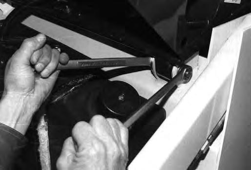
Have a second person hold the wrench on the nut in the chaincase [C].
Turn the nut on the outside of the axle tube until the inner bearing cup is on its seat.
NOTE:Pack the inner and outer axle bearing with grease before installing the axle assembly.
Install
MEL1052 – Seal Installation Tool
AXLES, SEALS AND BEARINGS (Cont’d)
Installation (Cont’d)
Install the outer halves of the tool on the inner halves[A].
Install the spring on the tool halves [B]
Put the drive chain on the reduction gear case sprocket.
Put the rear sprockets in the rear drive chain with the side part of the hub toward the outside of the chaincase [C]
Slide the axle into the chaincase, move the sprocket and chain to the rear of the chaincase and align it with the splines on the axle.
Slide the sprocket on the axle.
AXLES, SEALS AND BEARINGS (Cont’d)
Installation (Cont’d)
Using a large hammer, hit the axle hub until it is in the correct position. The tool will control the position of the axle and the seal will be in the correct location in the housing [A]
Remove the spring from the tool. Remove the outer halves of the tool. Remove the inner halves from the axle [B].
Use the same procedure to install the front axle.
Install the washer and bolt (inside the chaincase) on the axle.
Tighten the sprocket bolt to 300 ft.–lbs. (409 Nm) torque.
Center the reduction gearcase between the front and rear drive chains. Tighten the bolts to 220–245 ft.–lbs. (300–330 Nm) torque [C]
Check the axle end play. It must not exceed 0.013 inch (0,33 mm).
If end play is not correct replace the washer at the sprocket bolt to get the correct end play. (See Parts Microfiche.)
Install the transmission covers. (See Page 4–2.)
Install the brake linkage.
Install the center steering controls and linkages.
FINAL DRIVE CHAIN Removal and Installation
The tools listed will be needed to do the following procedure:
MEL1046 – Chain Breaker
MEL1037 – Chain Link Tool
MEL1049 – Chain Puller Tool
Lift and block the loader.
Remove the seat assembly.
Remove the center transmission shields.
Remove the chaincase covers. (See Page 4–2.)
Remove the fluid from the chaincase using a transfer pump.
Break the front chain [A]
MEL1046 – Chain Breaker
Remove the chain [B].
Break the rear drive chain [C]
MEL1046 – Chain Breaker
Remove the chain.
FINAL DRIVE CHAIN (Cont’d)
Removal and Installation (Cont’d)
Wear safety glasses to prevent eye injury when any of the following conditions exist:
• When fluids are under pressure.
• Flying debris or loose material is present.
• Engine is running.
• Tools are being used.
W–2019–1285
Install the replacement chain over the rear sprocket. Use the chain puller tool (Inset) to install the connector link in the chain [A].
MEL1049 – Chain Puller Tool
DO NOT exceed the recommended torque of 130 ft.–lbs. (176 Nm). The tool may fail undertoo much torque. Put cloth around the tool to protect yourself from flying debris.
W–2233–0296
Use the chain link press to crimp the connector link into position [A].
MEL1037 – Chain Link Tool
Be sure to use the adapter to #80 chain. Use a large wrench to hold the tool while pressing the chain link.
Use the same procedure to install the front drive chain.
REDUCTION GEARCASE Removal and Installation
Lift and block the loader.
Remove the hydrostatic motor.
Remove the seat assembly.
Remove the front panel and steering levers.
Remove the chaincase covers and brake assembly.
Drain the fluid from the chaincase and remove the front chain. (See Page 4–10.)
Support the reduction gearcase with a floor jack [A]
Remove the gearcase mounting bolts [B]
Installation: Tighten the bolts to 220–245 ft.–lbs. (300–330 Nm) torque.
Remove the bolt (Item 1) [C] and washer (Item 2) [C]
Drive the sprocket (Item 3) [C] through the gearcase into the chaincase so it clears the bearing (item 4) [C]
Remove the rear chain from the sprocket and lower the gearcase to the floor.
Installation: When reassembly of the gearcase is complete, replace the bolt (Item 1) [C] with a 1 inch (25,4 mm) longer bolt.
Install the longer bolt and washer (Item 2) [C] in the gearcase.
Lift the gearcase into position, angle the sprocket and install the rear drive chain on the sprocket.
Drive the sprocket inward until it clears the bearing (Item 4) [C]. Do not damage the 1 inch longer bolt.
Pull the gearcase sprocket into position with the longer bolt and remove the bolt.
Put thread sealant on the original bolt (Item 1) [C] and install as shown.
Tighten the bolt to 210–235 ft.–lbs.(285–305 Nm) torque.
Install the front chain. (See Page 4–11.)
REDUCTION GEARCASE (Cont’d)
Checking Reduction Gearcase
Before disassembly of the gearcase do the following checks:
Install a dial indicator on the input shaft[A]. The end play must be between 0.00–0.010 inch (0,0254 mm). If not, the following parts may need replacing: Bearing, bearing cups, gear or gearcase housing.
Install the dial indicator on the output shaft [B]. The end play must be between 0.00–0.010 inch (0,0254 mm). If not, the following parts may need replacing: Bearing, bearing cups, gear or gearcase housing.
Remove the seal.
Install a feeler gauge between the teeth of the gears[C]
The back lash must be between 0.003–0.009 inch (0,076–0,228 mm). If not, the following parts may need replacing: Large gear or the shaft.
Disassembly and Assembly
The tool listed will be needed to do the following procedure:
MEL1047 – Seal Installation Tool
Remove the bolts from the end plate [D]
Installation: Tighten the bolts to 13–14 ft.–lbs. (16–18 Nm) torque.
REDUCTION GEARCASE (Cont’d)
Disassembly and Assembly (Cont’d)
Remove the end plate [A]
Remove the dust cap [B]
Installation: Put Boretite sealant on the edge of the dust cap before installing it.
Remove the bolt from the output shaft [C]
Installation: Put LOCTITE #242 on the bolt and tighten to 210–235 ft.–lbs. (285–305 Nm) torque.
Remove the bolt and washer [D].
REDUCTION GEARCASE (Cont’d)
Disassembly and Assembly (Cont’d)
Remove the bolt at the disc hub [A].
Installation: Put LOCTITE #242 on the bolt and tighten to 210–235 ft.–lbs. (285–305 Nm) torque.
Remove the bolt and washer [B].
Remove the disc hub and key [C]
REDUCTION GEARCASE (Cont’d)
Disassembly and Assembly (Cont’d)
Remove the bearing [A].
Remove the spacer [B]
Remove the output shaft [C]
Remove the large gear [D].
REDUCTION GEARCASE (Cont’d)
Disassembly and Assembly (Cont’d)
Remove the bearing from the input shaft end [A].
Use a press and remove the input shaft [B].
Remove the input shaft assembly from the housing [C]
Use a punch and hammer and remove the bearing cups as needed [D]
Installation: Use a press and bearing cup driver to install the bearing cup.
REDUCTION GEARCASE (Cont’d) Reduction Gearcase Seal
The tool listed will be needed to do the following procedure:
MEL1047 – Seal Installation Tool
It is not necessary to remove the reduction gearcase. To replace the seal on the input shaft, use the following procedure.
Lift and block the loader. Remove the hydrostatic motor. Use a punch and hammer to bend the edge of the seal inward [A]
Use a screwdriver, pry the seal from the housing [B]
Remove the washer.
Measure the bore diameter for the seal [C]. Correct diameter is 3.750 ± 0.001 inch (95,25 ± 0,025 mm).
Install a dial indicator on the input shaft. Set the indicator stylus against the inside of the pilot bore for the drive motor. Rotate the shaft 360 °. Maximum run–out should not exceed 0.009 inch (0,229 mm).
If either bore I.D. or run–out is not within the specifications, replace the gearcase.
Remove the Quad–ring (Item 1) [D].
Installation: Install a new Quad–ring. Measure the new washer O.D. before installing it. Maximum O.D. is 3.745 inch (95,12 mm). The washer should be free of rough edges and burrs and slide into the bore freely.
REDUCTION GEARCASE (Cont’d)
Installation
Put Boretite sealant around the new seal.
Install the new seal using the seal installation tool (MEL1074) [A]
NOTE:Always use new O–rings when installing the reduction gearcase.
Put grease on the O–ring and install it on the outside of the gearcase [B] & [C].
NOTE:There are two different types of gearcase housings used, some later units used a retaining ring instead of a groove [C].
Install the retainer. Some later type uses sealant to hold the retainer ring.
Put the reduction gearcase on a jack and lift it into position [D].
Install the five bolts inside the chaincase. Do not tighten. Install the final drive chains. (See Page 4–10.)
Move the reduction gearcase backward or forward toget the same amount of chain play and equaltension on both chains.
REDUCTION GEARCASE (Cont’d)
Installation (Cont’d)
Tighten the five bolts to 220–245 ft.–lbs. (300–330 Nm) torque.
Install the hydrostatic motor [B].
Install the bolts and tighten to 65–70 ft.–lbs. (88–95 Nm) torque.
Connect the hoses to the motor and tighten.
Install the motor cover.
Install the transmission covers and the brake assembly. (See Page 4–12.)
Chaincase Fluid
Replacing Chaincase Fluid
Remove the front transmission cover. (See Page 4–2.)
Use a pump to remove all the fluid from the chaincase[C]
MEL10628 – Hydraulic Transfer Pump
Use clean rags to remove any fluid that the pump did not remove and to clean the chaincase [D]
Use only recommended replacement fluid. Bobcat Fluid (P/N 6563328) or 10W–30 or 10W–40 Class SE Motor Oil to fill the chaincase with 9 gals. (34 L) of fluid.
Install the front transmission cover. (See Page 4–2.)
TIGHTEN ALL HARDWARE PER SIZE TO GRADE 5 TORQUE (SEE STANDARD TORQUE SPECIFICATIONS FOR BOLTS, SECTION 9) UNLESS OTHERWISE SPECIFIED.
OPERATOR CAB (S/N 19999 & Below)
Removal And Installation
Lift and block the loader. (See PREVENTIVE MAINTENANCE Section 1 for the correct procedure.)
Disconnect the electrical harness [A]
A
B–04696
Raise the operator cab.
Fasten a chain and chain hoist to the operator cab [B].
Remove the bolt and nut at the spring block. Remove the spring block (both sides) [C]
Installation: Tighten the bolt and nut to 65–70 ft.–lbs. (88–95 Nm) torque.
Remove the nuts at the pivot bolt for the operator cab (both sides) [D].
OPERATOR CAB (S/N 19999 & Below) (Cont’d)
Removal And Installation (Cont’d)
With the chain hoist tight.
Use a punch and hammer and remove the bolts (both sides) at the pivot bracket [A]
Use a pry bar, pry the springs out of the operator cab[B].
Lift the operator cab with the chain hoist and remove it from the loader.
OPERATOR CAB (S/N 20001 & Above)
Removal And Installation
Remove the stop blocks at the rear of the operator cab [A]
After the stop blocks are removed and the operator cab has a rear window, REMOVE THE REAR WINDOW to prevent damage to the rear window.
Raise the operator cab. (See PREVENTIVE MAINTENANCE Section 1 for the correct procedure.)
Disconnect the electrical harness [B]
Remove the electrical harness clamp [C]
Install a bar through the operator cab balance point. Install a chain and chain hoist [D].
OPERATOR CAB (S/N 20001 & Above) (Cont’d)
Removal And Installation (Cont’d)
Remove the clip at the upper pivot pin for the gas cylinder [A]
Remove the upper pivot pin for the gas cylinder (both sides) [B]
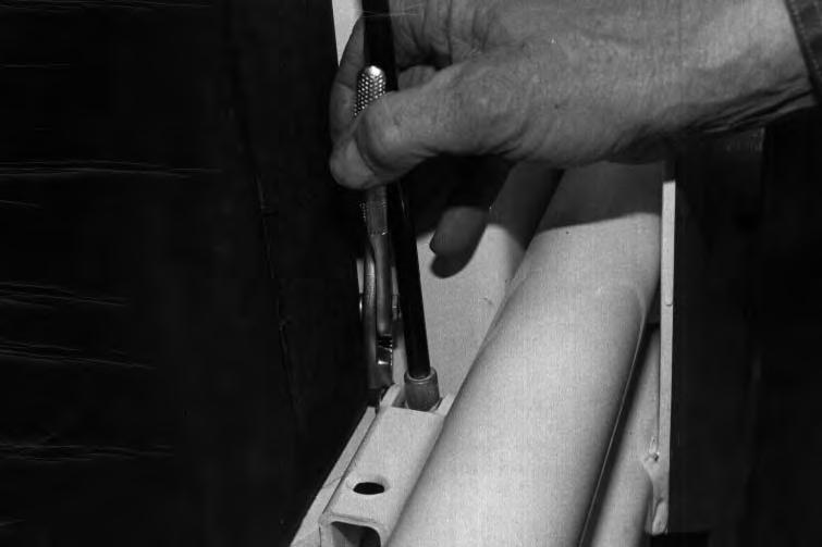
Installation: Install the lower pivot pin first, use a screwdriver to hold the gas cylinder and install the top pivot pin.
Remove the clip at the lower pivot pin [C]
Remove the lower pivot pin (both sides) [D].
OPERATOR CAB (S/N 20001 & Above) (Cont’d)
Removal And Installation (Cont’d)
Remove the gas cylinder (both sides) [A].
Remove the nuts from the pivot bolts [B].
Installation: Tighten the pivot bolts to 25–35 ft.–lbs. (34–47 Nm) torque.
Use a punch to remove the pivot bolt (both sides) [C]
Lift the operator cab from the loader using the chainhoist.
REAR DOOR Removal And Installation
Install a chain hoist on the rear door [A].
Use a punch and hammer, remove both hinge pins [B]. Lift the door from the loader frame.
REAR DOOR (Cont’d)
Door Latch Adjustment
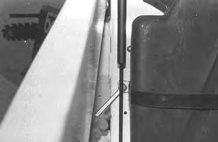
Loosen the set screw [A]
Loosen the nut (Item 1) [B]
Turn the bolt (Item 2) [B] in or out, until the door contacts both the top and bottom of the loader frame (Item 1) [C] with the lever in the latched position.
NOTE:It takes approximately 50 lbs. of force to push the lever down when the latch is adjusted correctly.
With the set screw up, the flanges at the bolt (Item 2)[C] must be to the sides so that the set screw aligns with the flat surface at the end of the bolt [C]
Tighten the set screw [A]
Tighten the nut (Item 1) [B] to 65–70 ft.–lbs. (88–95 Nm) torque.
Lift Arms
Removal And Installation
Lift and block the loader. (See PREVENTIVE MAINTENANCE Section 1 for the correct procedure.)
Roll the Bob–Tach frame fully forward.
Stop the engine. Activate the hydraulic controls to release the hydraulic pressure.
Remove the Bob–Tach frame. (See Page 5–11.)
Fasten chains and chain hoist to the lift arms [A]
Put a floor jack under the lift arms [B].
Raise the lift arms, with the floor jack, until the pivot pin at the rod end of the lift cylinder can be removed.
Remove the lock nut and bolt [C]
Installation: Tighten the bolt and nut to 18–20 ft.–lbs. (24–27 Nm) torque.
Remove the pins at the rod end of the lift cylinder (both sides) [D]
Lower the lift arms. Remove the floor jack.
LIFT ARMS (Cont’d)
Removal And Installation (Cont’d)
Remove the lock nut and bolt [A].
Installation: Tighten the bolt and nut to 18–20 ft.–lbs. (24–27 Nm) torque.
Tighten the chain hoist.
Use a punch and soft hammer, remove the pivot pin at the lift arm (both sides) [B]
Raise the lift arms with the chain hoist and remove them from the loader frame.
BOB–TACH
Removal And Installation
Tilt the Bob–Tach fully forward until the front edge is on the floor [A].
Stop the engine. Move the hydraulic controls to release the hydraulic pressure.
Remove the lock nut and bolt at the rod end of the tilt cylinder [B].
Installation: Tighten the bolt and nut to 18–20 ft.–lbs. (24–27 Nm) torque.
Remove the pivot pin at the rod end of the tilt cylinder[C].
Loosen the bolt at the Bob–Tach pivot pin [D]. DO NOT remove the bolt.
Installation: Tighten the bolt at the pivot pin to 125–140 ft.–lbs. (1701–190 Nm) torque.
BOB–TACH (Cont’d)
Removal And Installation (Cont’d)
Remove the grease fitting at the pivot pins [A].
NOTE:The grease fitting at the pivot pin must be removed, because the grease can cause a lock and the pivot pin cannot be removed from the Bob–Tach frame.
Put a rag over the grease fitting hole.
Hit the bolt to start the pivot pin into the Bob–Tach frame [B]
Remove the bolt and use a punch to push the pivot pininto the Bob–Tach frame.
Repeat the above procedure for the other side.
Installation: Use a small diameter punch through the grease fitting hole to push the pivot pin into the lift arms.
Remove the Bob–Tach from the lift arms.
Remove the Bob–Tach pivot pins [C]
Tilt Cylinder Rod End Seal
After the Bob–Tach is installed on the lift arms, use this procedure to install the rod end seals.
Lift the Bob–Tach with a floor jack [D]
BOB–TACH (Cont’d)
Removal And Installation (Cont’d)
Install the new seals at the rod end [A].
Put a piece of shim stock on each side of the seals [B]
Lift the Bob–Tach with the floor jack and install the rod end into the Bob–Tach frame [B]
Remove the shim stock and finish installing the Bob–Tach.
Disassembly And Assembly
Put the Bob–Tach on a work bench.
Remove the bolt at the Bob–Tach lever [C].
Installation: Tighten the bolt to 25–28 ft.–lbs. (34–38 Nm) torque.
Using a punch and hammer, remove the Bob–Tach wedge and spring assembly from the frame [D]
BOB–TACH (Cont’d)
Disassembly And Assembly (Cont’d)
Put the wedge and lever assembly in the vise.
Remove the bolt at the lever [A]
Assemble: Tighten the bolt to 25–28 ft.–lbs. (34–38 Nm) torque.
A
Remove the block from the wedge bolt [B]
Assemble: Turn the block down until there is 6.390’’ (162 mm) from the center of the hole to the top of the wedge spring seat [B]
Remove the nut and the spring from the bolt [C]
Remove the plastic guides from the Bob–Tach frame [D]
Clean and inspect all the parts for wear and damage, replace the parts as needed.
FUEL TANK (S/N 19999 & Below)
Removal And Installation
Raise the operator cab. (See PREVENTIVE MAINTENANCE Section 1 for the correct procedure.)
Disconnect the wire from the operator cab harness connector [A]
Turn the fuel shutoff valve to the OFF position. Use a transfer pump and remove all the fuel from the tank.
FUEL TANK (S/N 20001 & Above)
Removal And Installation
Raise the operator cab. (See PREVENTIVE MAINTENANCE Section 1 for the correct procedure.)
Use a transfer pump to remove the fuel fromthe fuel tank. Remove the harness plate screws at the top of the fuel tank [A]
Move the harness plate over and above the hydraulic reservoir. Disconnect the wires at the fuel sender [B].
Remove the fuel hoses from the tank fittings [C].
Remove the fuel hoses at the shutoff valve [D]
FUEL TANK (S/N 20001 & Above) (Cont’d)
Removal And Installation (Cont’d)
Remove the fuel tank holding strap bolt [A].
Remove the fuel tank from the loader.
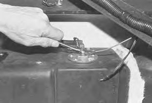
Fuel Tank Sender Switch
Remove the harness plate from the top of the fuel tank [B]
Remove the wires from the sender.
Remove the screws from the sender [C]
Remove the sender switch from the fuel tank [D]
TIGHTEN ALL HARDWARE PER SIZE TO GRADE 5 TORQUE (SEE STANDARD TORQUE SPECIFICATIONS FOR BOLTS, SECTION 9) UNLESS OTHERWISE SPECIFIED.