Fuel/Lubrication/Cooling
! WARNING
! WARNING Whenever any maintenance or inspection is performed on the fuel system during which there may be fuel leakage, there should be no welding, smoking, open flames, etc., in the area.
NOTE: The manufacturer recommends the use of
new gaskets, lock nuts, and seals and lubricating all internal components when servicing the engine/transmission. SPECIAL TOOLS
A number of special tools must be available to the technician when performing service procedures in this section. Refer to the current Special Tools Catalog for the appropriate tool description. NOTE: When indicated for use, each special tool
will be identified by its specific name, as shown in the chart below, and capitalized. Description Oil Pressure Test Kit Seal Removal Tool Tachometer
Throttle Body
p/n 0644-495 0644-072 0644-275
NOTE: Special tools are available from the Service Department. TROUBLESHOOTING
1. Verify that the electric fuel pump is operating by listening for a “whirring” sound for several seconds after the ignition switch is turned to the ON position. If no sound can be heard, see Electrical System - EFI Sensors/Components. 2. Check for a flashing DTC (Diagnostic Trouble Code) on the LCD. If a code is flashing, see EFI Sensors/Components in Electrical System.
Whenever any maintenance or inspection is performed on the fuel system during which there may be fuel leakage, there should be no welding, smoking, open flames, etc., in the area.
REMOVING
1. Turn the ignition switch to the OFF position; then remove the ignition switch key.
! WARNING Do not turn the ignition switch to the ON position with the hoses removed. Gasoline will be pumped by the electric fuel pump causing a safety hazard.
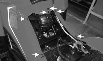
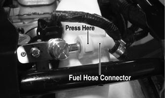
2. Remove the seats and tool tray; then disconnect the battery. 3. Remove the storage compartment cover, front storage compartment, and side panels. 4. Loosen the clamps securing the air filter housing boot to the throttle body inlet and air box; then remove the boot from the throttle body. 5. Disconnect the IAT sensor connector from the air box. Remove the spark plug cap from the spark plug; then disconnect the primary lead from the ignition coil. Remove the crankcase breather hose from the bottom right side of the air box; then remove the air box assembly. 6. Slowly disconnect the fuel hose connector from the fuel rail.
! WARNING Gasoline may be under pressure. Place an absorbent towel under the connector to absorb any gasoline spray when disconnecting.
3. Make sure there is sufficient, clean gas in the gas tank.
XR296A
7. Remove the screws securing the throttle actuator cover to the throttle body; then remove the cover. Note the installed length of the throttle cable housing to the throttle body to aid in re-assembly. 8. Loosen the outer jam nut securing the throttle cable to the throttle body. Remove the throttle cable from the actuator arm; then route the cable out of the way. 85