18 minute read
Periodic Maintenance/Tune-up

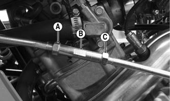
Tighten all nuts, bolts, and cap screws. Make sure rivets holding components together are tight. Replace all loose rivets. Care must be taken that all calibrated nuts, bolts, and cap screws are tightened to specifications (see General Information/Foreword). It is advisable to lubricate certain components periodically to ensure free movement. Apply light oil to the components using the following list as reference: A.Throttle Lever Pivot B.Brake Lever Pivot C.Auxiliary Brake Pedal Pivot NOTE: The manufacturer recommends the use of new gaskets, lock nuts, and seals and lubricating all internal components when servicing the engine/transmission.
SPECIAL TOOLS A number of special tools must be available to the technician when performing service procedures in this section. NOTE: When indicated for use, each special tool will be identified by its specific name, as shown in the chart below, and capitalized.
Description p/n
Compression Tester Kit 0444-213 Drive Belt Gauge 0444-177 Oil Filter Wrench 0644-389 Spanner Wrench 0444-240 Valve Clearance Adjuster 0444-255
NOTE: Special tools are available from the Service Department.
Air Filter
The air filter inside the air filter housing must be clean to provide good engine power and gas mileage. If the ATV is used under normal conditions, service the filter at the intervals specified in the Maintenance Schedule. If operated in dusty, wet, or muddy conditions, inspect and service the filter more frequently.
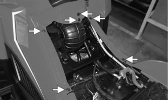
1.Remove the seat; then lift the front storage box lid.
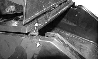
Gently pull out on the side panel plastics to free the storage box lid base tabs from the side panel plastics.
Repeat for opposite side. Remove the storage box lid and base. CAUTION
Failure to inspect the air filter frequently if the ATV is used in dusty, wet, or muddy conditions can damage the engine.
XR236A
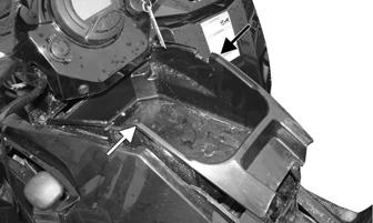
2.Release the front storage tray by lightly squeezing the left and right outside edges inward.
XR237A
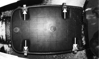
3.Release the four retaining clips to remove the air box lid. Remove the air filter frame and air filter. Note the orientation of the air box lid, air filter, and frame for assembly purposes.
XR239A
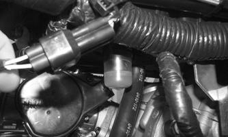
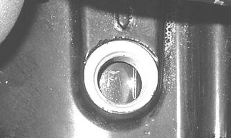
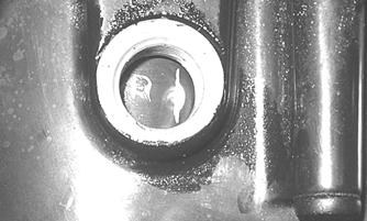
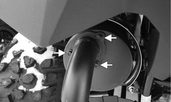
4.With the filter removed, place the filter in a pan larger than the element and spray both sides generously with Cleaning Solvent; then let sit approximately three minutes. 5.In a pan larger than the element, with a mild detergent (dish soap) and water, wash all the dirt and oil off by squeezing the element, not twisting it (wringing out or twisting the filter can cause damage). 6.Rinse off any remaining soap. 7.Remove any excess water from the element by matting with a towel. 8.Allow the element to dry completely. 9.Spray oil generously onto air filter and work the oil into the element. 10.Squeeze the element to remove excess oil. 11.Install the air filter and frame back into the air box; then secure with the air filter lid. 12.Install the storage tray, storage tray base, and lid; then install the seat. CHECKING AND CLEANING DRAINS 1.Inspect the drains beneath the main housing for water/oil and for proper sealing.
XR260
2.Replace any drain that is cracked or shows any signs of hardening or deterioration.
3.Wipe any accumulation of oil or gas from the filter housing and drains.
CAUTION
The drain to the rear of the airbox is the clean air section of the filter housing. Any leak of this drain will allow dirt into the engine intake causing severe engine damage.
Valve/Tappet Clearance
NOTE: The seat, storage compartment cover assembly, compartment box, air filter/filter housing, and left-side/right-side splash panels must be removed for this procedure. To check and adjust valve/tappet clearance, use the following procedure: 1.Remove the timing inspection plug; then remove the tappet covers and spark plug(s) (for more detailed information, see Engine/Transmission — Servicing
Top-Side Components). 2.Rotate the crankshaft to the TDC position on the compression stroke.
GZ063
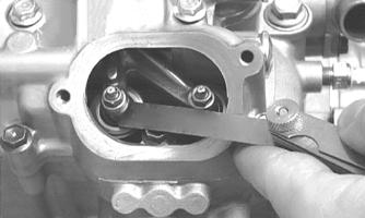
NOTE: At this point, the rocker arms and adjuster screws must not have pressure on them. 3.Align the timing mark to the magneto cover mark. CHECKING Using a feeler gauge, check each valve/tappet clearance. If clearance is not within specifications, loosen the jam nut and rotate the tappet adjuster screw until the clearance is within specifications. Tighten each jam nut securely after completing the adjustment.
CAUTION
The feeler gauge must be positioned at the same angle as the valve and valve adjuster for an accurate measurement of clearance. Failure to measure the valve clearance accurately could cause valve component damage.
VALVE/TAPPETCLEARANCE
700 0.08-0.12 mm (0.003-0.005 in.) – Intake 0.13-0.17 mm (0.005-0.007 in.) – Exhaust
CC007D
ADJUSTING A.Place Valve Clearance Adjuster onto the jam nut securing the tappet adjuster screw; then rotate the valve adjuster dial clockwise until the end is seated in the tappet adjuster screw. B.While holding the valve adjuster dial in place, use the valve adjuster handle and loosen the jam nut; then rotate the tappet adjuster screw clockwise until friction is felt. C.Align the valve adjuster handle with one of the marks on the valve adjuster dial. D.While holding the valve adjuster handle in place, rotate the valve adjuster dial counterclockwise until proper valve/tappet clearance is attained. NOTE: Refer to the appropriate specifications in CHECKING for the proper valve/tappet clearance. NOTE: Rotating the valve adjuster dial counterclockwise will open the valve/tappet clearance by 0.05 mm (0.002 in.) per mark. E.While holding the adjuster dial at the proper clearance setting, tighten the jam nut securely with the valve adjuster handle.
GZ059
F.Install the spark plugs and timing inspection plug. NOTE: Apply grease to the end cap to aid in installation.
G.Place the tappet covers into position making sure the proper cap screws are with the proper cover. Tighten the cap screws securely.
Testing Engine Compression
1.Remove the high tension lead from the spark plug. 2.Using compressed air, blow any debris from around the spark plug.
3.Remove the spark plug; then attach the high tension lead to the plug and ground the plug on the cylinder head well away from the spark plug hole. 4.Attach the Compression Tester Kit.
! WARNING
Always wear safety glasses when using compressed air.
NOTE: The engine should be warm (operating temperature) and the battery fully charged for an accurate compression test. Throttle must be in the wide-open throttle (WOT) position. In the event the engine cannot be run, cold values are included. 5.While holding the throttle lever in the full-open position, crank the engine over with the electric starter until the gauge shows a peak reading (five to 10 compression strokes).
COMPRESSION Model Hot (WOT) Cold (WOT)
700 125-145 psi 100-140 psi
6.If compression is abnormally low, inspect the following items:
A.Verify starter cranks engine over at normal speed (approximately 400 RPM). B.Gauge functioning properly. C.Throttle lever in the full-open position. D.Valve/tappet clearance correct. E.Engine warmed up. F. Intake not restricted.
NOTE: To service valves, see Engine/Transmission. 7.Pour 29.5 mL (1 fl oz) of oil into the spark plug hole, reattach the gauge, and retest compression. 8.If compression is now evident, service the top end (see Engine/Transmission).
Spark Plug
A light brown insulator indicates that a plug and the fuel/air ratio are correct. A white insulator indicates a lean running condition. A dark insulator indicates a rich running condition and that the engine may need to be serviced. To maintain a hot, strong spark, keep the plug free of carbon.
ATV-0051
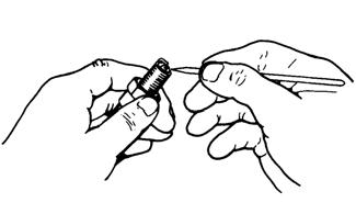
Before removing a spark plug, be sure to clean the area around the spark plug. Dirt could enter engine when removing or installing the spark plug.
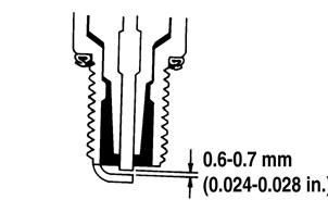
Adjust the gap to correct specification (see General Information/Foreword for proper type and gap). Use a feeler gauge to check the gap.
ATV0052
A new spark plug should be tightened 1/2-turn once the washer contacts the cylinder head. A used spark plug should be tightened 1/8-1/4 turn once the washer contacts the cylinder head.
Muffler/Spark Arrester
! WARNING
Wait until the muffler cools to avoid burns.
1.Remove the three cap screws securing the spark arrester assembly to the muffler; then loosen and remove the arrester. Account for the gasket and wave washer.
XR242A XR243A
2.Using a suitable brush, clean the carbon deposits from the screen taking care not to damage the screen. NOTE: If the screen or gasket is damaged in any way, it must be replaced. 3.Install the spark arrester assembly with gasket; then secure with the three cap screws. Tighten to 48 in.-lb (5.4 N-m).
Engine/Transmission Oil — Filter
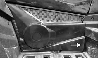
The engine should always be warm when the oil is changed so the oil will drain easily and completely. 1.Park the ATV on level ground. Remove the left side access panel by pulling outward on the bottom right side.
XR218A
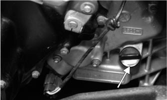
2.Remove the oil level stick/filler plug.
3.Remove the drain plug from the bottom of the engine and drain the oil into a drain pan. Account for and discard the drain plug gasket.
! WARNING
Use extreme caution when removing the oil drain plug. Hot oil can cause severe injury and skin burns.
733-441A
4.Using the adjustable Oil Filter Wrench and a suitable wrench, remove the old oil filter. Account for and discard the O-ring. NOTE: Clean up any excess oil after removing the filter. 5.Apply oil to the new filter O-ring and check to make sure it is positioned correctly; then install the new oil filter. Tighten securely. 6.Install the engine drain plug with new gasket and tighten to 16 ft-lb (21.8 N-m). Pour the specified amount of the recommended oil in the filler hole.
Install the oil level stick/filler plug.
CAUTION
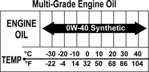
Any oil used in place of the recommended oil could cause serious engine damage. Do not use oils which contain graphite or molybdenum additives. These oils can adversely affect clutch operation. Also, not recommended are racing, vegetable, non-detergent, and castor-based oils.
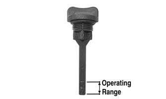
7.Start the engine (while the ATV is outside on level ground) and allow it to idle for a few minutes. 8.Turn the engine off and wait approximately one minute. 9.Remove the oil level stick and wipe it with a clean cloth. 10.Install the oil level stick and thread into the engine case. 11.Remove the oil level stick; the oil level must be within the operating range but not exceeding the upper mark.
XR234A
CAUTION
Do not over-fill the engine with oil. Always make sure that the oil level is not above the upper mark.
12.Inspect the area around the drain plug and oil filter for leaks. Install the access panel.
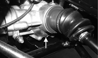
Front Differential/Rear Drive Lubricant
CAUTION
Any lubricant used in place of the recommended gear lube could result in premature failure of the shock limiter. Do not use any lubricant containing graphite or molybdenum additives or other friction-modified lubricants as these may cause severe damage to shock limiter components.
When changing the lubricant, use SAE-approved 80W-90 hypoid gear lube. To check lubricant, remove the fill plug; the lubricant level should be 1 in. below the threads of the plug. If low, add SAE-approved 80W-90 hypoid gear lubricant as necessary. To change the lubricant, use the following procedure: 1.Place the ATV on a level surface. 2.Remove the oil filler and oil level plugs. 3.Drain the oil into a drain pan by removing in turn the drain plug from each.
Front
XR019A
XR017A
4.After all the oil has been drained, install the drain plugs and tighten securely.
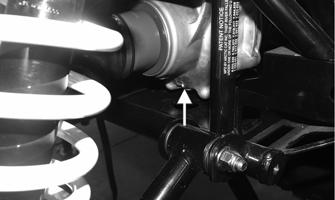
5.Pour recommended oil into each filler hole. The correct oil level is achieved when the oil level is flush with the bottom threads of the level plug hole.
CAUTION
Inspect the oil for any signs of metal filings or water. If found, take the ATV to an authorized ATV dealer for servicing.
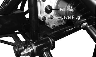
XR022A
NOTE: The manufacturer recommends the use of genuine lubricants. 6.Install the oil level and oil filler plugs.
Shift Lever
CHECKING ADJUSTMENT
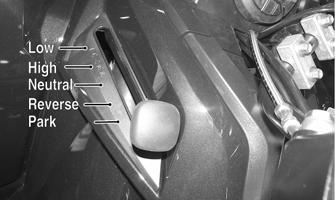
Never shift the ATV into reverse gear when the ATV is moving as it could cause the ATV to stop suddenly throwing the operator from the ATV.
ADJUSTING SHIFT LEVER 1.Remove the seat and left side panel. 2.With the ignition switch in the ON position, loosen jam nut (A) (left-hand threads); then loosen jam nut (C) and with the shift lever in the reverse position, adjust the coupler (B) until the transmission is in reverse and the (R) icon appears on the LCD.
XR261A
3.Tighten the jam nuts securely; then shift the transmission to each position and verify correct adjustment. 4.Install the left-side engine cover and seat making sure the seat locks securely in place. NOTE: An E (Error) in the gear position icon indicates no signal or a poor ground wire connection in the circuit. Troubleshoot the harness connectors, gear position switch connector, gear position switch, and LCD connector.
Hydraulic Brake Systems
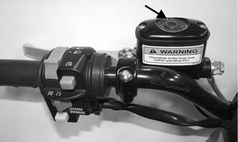
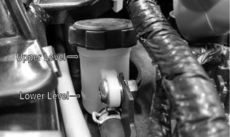
CHECKING/BLEEDING The hydraulic brake systems have been filled and bled at the factory. To check and/or bleed a hydraulic brake system, use the following procedure: 1.With the master cylinder in a level position, check the fluid level in the reservoir. On the hand brake if the level in the reservoir is adequate, the sight glass will appear dark. If the level is low, the sight glass will appear clear. On the auxiliary brake, the level must be between the MIN and MAX lines on the reservoir.
CF295A
XR222A
2.Compress the brake lever/pedal several times to check for a firm brake. If the brake is not firm, the system must be bled. 3.To bleed the main brake system, use the following procedure:
A.Remove the cover and fill the reservoir with DOT 4 Brake Fluid; then install and secure the cover.
B.Slowly compress the brake lever several times.
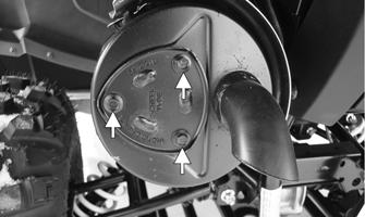
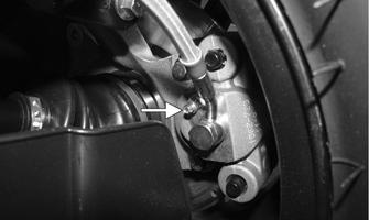
C.Remove the protective cap, install one end of a clear hose onto the REAR bleeder screw, and direct the other end into a container; then while holding slight pressure on the brake lever, open the bleeder screw and watch for air bubbles. Close the bleeder screw before releasing the brake lever. Repeat this procedure until no air bubbles are present.
XR262A
NOTE: During the bleeding procedure, watch the sight glass very closely to make sure there is always a sufficient amount of brake fluid. If low, refill the reservoir before the bleeding procedure is continued. Failure to maintain a sufficient amount of fluid in the reservoir will result in air in the system.
D.At this point, perform step B and C on the FRONT RIGHT bleeder screw; then move to the FRONT LEFT bleeder screw and follow the same procedure.
E.Repeat step D until the brake lever is firm. 4.To bleed the auxiliary brake system, use the following procedure:
A.Remove the cover and fill the reservoir with DOT 4 Brake Fluid; then install and secure the cover.
B.Slowly compress the brake pedal several times.
C.Remove the protective cap, install one end of a clear hose onto the rear bleeder screw, and direct the other end into a container; then while holding slight pressure on the brake pedal, open the bleeder screw and watch for air bubbles. Close the bleeder screw before releasing the brake pedal. Repeat this procedure until no air bubbles are present.
XR262A
NOTE: During the bleeding procedure, watch the reservoir very closely to make sure there is always a sufficient amount of brake fluid. If low, refill the reservoir before the bleeding procedure is continued. Failure to maintain a sufficient amount of fluid in the reservoir will result in air in the system.
D.Repeat step B and C until the brake pedal is firm. 5.Carefully check the entire hydraulic brake system that all hose connections are tight, the bleed screws are tight, the protective caps are installed, and no leakage is present.
CAUTION
This hydraulic brake system is designed to use DOT 4 brake fluid only. If brake fluid must be added, care must be taken as brake fluid is very corrosive to painted surfaces.
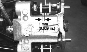
INSPECTING HOSES Carefully inspect the hydraulic brake hoses for cracks or other damage. If found, the brake hoses must be replaced. CHECKING/REPLACING PADS The clearance between the brake pads and brake discs is adjusted automatically as the brake pads wear. The only maintenance that is required is replacement of the brake pads when they show excessive wear. Check the thickness of each of the brake pads as follows. NOTE: As brake pads wear, it may be necessary to “top-off” the brake fluid in the reservoir. 1.Remove a front wheel. 2.Measure the thickness of each brake pad. 3.If thickness of either brake pad is less than 1.0 mm (0.039 in.), the brake pads must be replaced.
PR376B
NOTE: The brake pads should be replaced as a set. 4.To replace the brake pads, use the following procedure:
A.Remove the wheel.
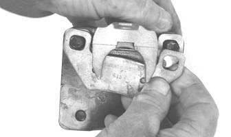
B.Remove the cap screws securing the caliper holder to the knuckle; then remove the pads.
PR237
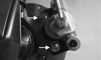
C.Install the new brake pads. D. Secure the caliper to the knuckle and/or axle housing with new “patch-lock” cap screws.
Tighten to 20 ft-lb (27.2 N-m).
XR263A
E.Install the wheel; then using a crisscross pattern, tighten the wheel nuts in 20 ft-lb (27.2 N-m) increments to a final torque of 40 ft-lb (54.4 N-m) (steel wheel), 60 ft-lb (81.6 N-m) (aluminum wheel w/black nuts), or 80 ft-lb (108.8 N-m) (aluminum wheel w/chrome nuts). 5.Burnish the brake pads (see Burnishing Brake Pads in this section).
Burnishing Brake Pads
Brake pads (both main and auxiliary) must be burnished to achieve full braking effectiveness. Braking distance will be extended until brake pads are properly burnished.
1.Choose an area large enough to safely accelerate the
ATV to 30 mph (48 km/h) and to brake to a stop. 2.Accelerate to 30 mph (48 km/h); then release the throttle lever and compress brake lever or apply the auxiliary brake to decelerate to 0-5 mph (0-8 km/h). 3.Repeat procedure on each brake system 20 times. 4.Verify that the brake light illuminates when the hand lever is compressed or the brake pedal is depressed.
! WARNING
Failure to properly burnish the brake pads could lead to premature brake pad wear or brake loss. Brake loss can result in severe injury or death.
Checking/Replacing V-Belt
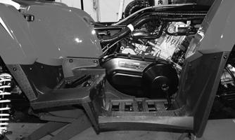
REMOVING 1.Remove the right side panel, right side footrests and footwell, and brake pedal (see Steering/Body/Controls).
XR264
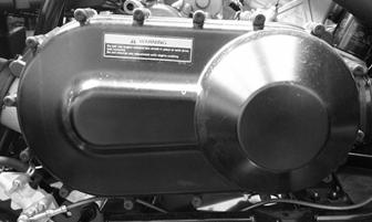
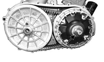
2.Remove the cap screws securing the CVT cover; then using a rubber mallet, gently tap on the cover tabs to loosen the cover. Remove the cover. Account for two dowel pins. NOTE: Some models use fibrous washers; account for these when used.
CD966A
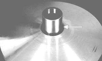
4.Install the cap screw from the tool kit into the driven pulley fixed face; then turn the cap screw clockwise to spread the pulley faces. Remove the V-belt.
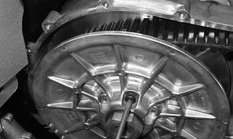
XR265
3.Remove the nut securing the movable drive face; then remove the face. Account for the flat washer and spacer. NOTE: Keep the drive faceplate in contact with the drive face when removing or installing the drive face to prevent the rollers from falling out.
CF364A GZ076
GZ085
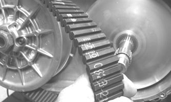
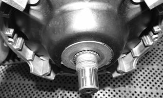
CHECKING Use the Drive Belt Gauge to identify any abnormal wear. Measure across the top of the V-belt (in multiple locations) using a Vernier caliper. Do not squeeze the belt as doing so may produce an inaccurate measurement. The V-belt must be at least 35.0 mm at any point. INSTALLING 1.Place the V-belt into position on the driven pulley and over the front shaft.
GZ085
NOTE: The arrows on the V-belt should point in direction of engine rotation (forward). 2.Pinch the V-belt together near its center and slide the spacer and movable drive face onto the front shaft.
Secure the drive face with a washer and nut (coated with red Loctite #271). Using an appropriate spanner wrench, tighten the nut to 162 ft-lb (220 N-m).
CAUTION
Make sure the movable drive faceplate is fully engaged onto the splines of the clutch shaft before tightening the nut or false torque readings may occur. This will cause the assembly to loosen damaging the shaft and clutch faceplate.
CF379
NOTE: At this point, the cap screw can be removed from the driven pulley. 3.With the vehicle in neutral, rotate the V-belt and clutches counterclockwise until the V-belt is flush with the top of the driven pulley. 4.Place the CVT cover gasket into position; then install the cover and secure with the cap screws. Tighten to 45 in.-lb (5 N-m) (5 mm shouldered fibrous washers) or 9.5 ft-lb (12.9 N-m) (6 mm cap screws). 5.Install the right side footwell, footrests, and right side panel (see Steering/Body/Controls). Tighten the brake pedal cap screw to 25 ft-lb (34 N-m).