28 minute read
Steering/Body/Controls

The following steering components should be inspected periodically to ensure safe and proper operation: A.Handlebar grips not worn, broken, or loose. B.Handlebar not bent, cracked, and has equal and complete full-left and full-right turning capability. C.Steering post bearing assembly/bearing housing not broken, worn, or binding. D.Ball joints not worn, cracked, or damaged. E.Tie rods not bent or cracked.
F.Knuckles not worn, cracked, or damaged. G.Cotter pins not damaged or missing. The frame, welds, and racks should be checked periodically for damage, bends, cracks, deterioration, broken components, and missing components.
Front Body Panel/Side Panels/Rack
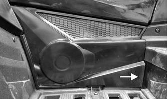
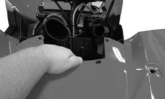
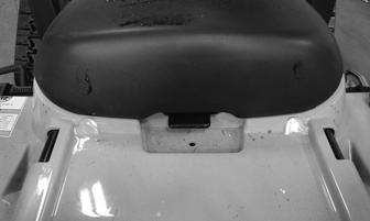
NOTE: The technician should use sound judgment and discretion when determining which components require removing to service a particular component. REMOVING 1.Remove both seats, the front storage tray lid/base, and front storage tray. 2.Grasp the bottom right side of the left access panel and remove it.
XR246A
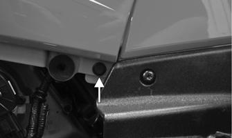
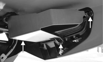
4.Remove the cap screws securing the steering post cover to the side panels; then remove the steering post cover. Remove the cap screws securing both side panels to the front body panel.
XR247A
XR248A
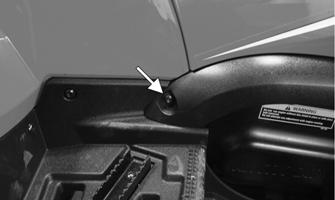
5.From the left side, remove the shift lever knob and the remaining reinstallable rivet to remove the left side panel.
XR218A
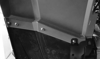
3.Remove the reinstallable rivets securing both side panels to each other and to the frame.
XR249A
6.From the right side, remove the remaining cap screw to remove the right side panel.

XR250A
7.Remove the four lock nuts securing the front rack assembly to the frame.
XR268A
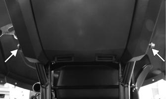
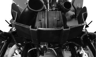
10.On each side of the vehicle, remove the cap screws and lock nuts securing the front fender plastics to the front of the footwells.
XR266
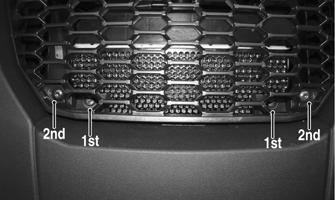
8.Remove the two self-tapping screws securing the front grille and the two cap screws located behind the grille securing the front fascia to the bumper frame.
XR269
11.From the front of the vehicle, grasp the top of the fender assembly and the bottom of the front fascia.
Remove by pulling up and away from the vehicle.
XR267A
9.Disconnect the headlight connectors from the back of the headlights; then remove the two lower cap screws securing the bottom of the front fascia to the front of the frame. Release the front fascia from the front of the frame.

XR270
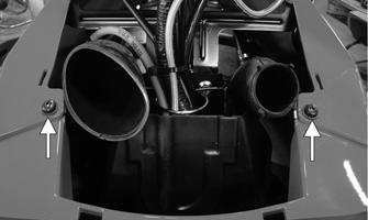
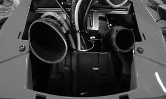
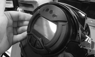
NOTE: The following steps are used to remove the headlights, front fascia, and front bumper. 12.To remove the headlights from the front fascia, remove the two rubber bands and the adjuster screw from each headlight assembly. To free the headlight assembly, pull rearward away from of the front fascia.
XR271A
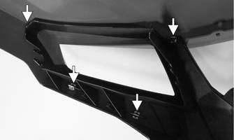
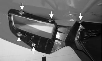
13.Remove the six remaining retaining clips and two self-tapping cap screws to remove the front fascia from the front fender assembly.
XR273
2.Secure the front fascia to the front fender and secure using the six retaining clips and two self-tapping screws.
XR272A
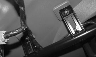
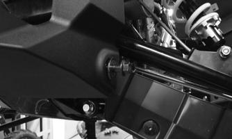
14.Remove the two headlight wire-forms from the frame; then remove the two remaining cap screws and lock nuts securing the front bumper to the frame.
XR272A
3.Secure the headlight assemblies into the front fascia using the two rubber bands and the adjuster screws.
XR273
CLEANING AND INSPECTING 1.Clean all components with warm soap and water. 2.Inspect for cracks and/or loose rivets. 3.Inspect for any missing decals. INSTALLING 1.Place the front bumper onto the frame; then install the cap screws with new lock nuts. Finger tighten only at this point.
XR271A
4.Place the front fender assembly onto the vehicle. Spread the bottom of the front fascia outward to seat over the bottom of the front bumper. Tighten the cap screws securing the front fascia/front bumper to the frame.
5.Tighten the bumper cap screws (from step 1) to 35 ft-lb (47.6 N-m). 6.Align the front fender to the front side of the footwells; then secure the cap screws and lock nuts.
XR248
XR269
7.Secure the front fascia to the bumper frame using the two cap screws; then place the grille into position and secure with the two self-tapping screws.
XR247A
10.Install the plastic rivets to secure each side panel together and to the frame.
XR267B
8.Place the front rack assembly over the front fender.
Guide the threaded studs through the frame; then secure the rack with new lock nuts. Tighten the nuts to 20 ft-lb (27.2 N-m).
XR266
9.Install both side panels. Secure the side panels to the front fender assembly with two cap screws. Install the steering post cover and secure with the two cap screws.
XR246A
11.Install the left access panel, front storage tray, storage tray lid/base, and both seats; then connect the headlights to the wiring harness. 12.Check headlight alignment (see Headlights/Taillights/Brake Lights).
Rear Body Panel/Rack
REMOVING 1.Remove the seats; then remove the gas tank cap.
Remove both side panels (see Steering/Body/Controls). 2.Remove the battery cover. Disconnect the negative cable; then disconnect the positive cable. Remove the battery. Remove the steel battery support from the battery tray.
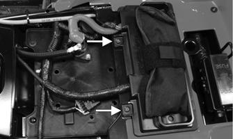
XR274A
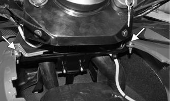
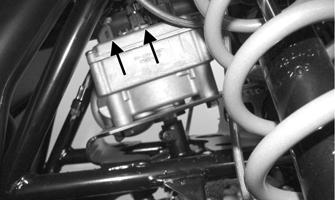
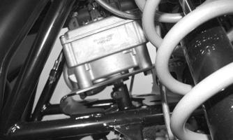
3.Remove the two cap screws securing the top of the rear body panel to the frame located behind the
PDM.
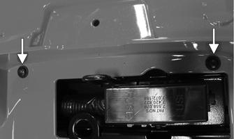
XR275A
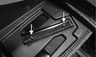
4.Remove the four lock nuts securing the rear rack assembly to the frame (two from each side); then remove the rear rack assembly.

XR276A
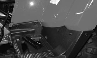
5.Remove the cap screws and lock nuts securing both passenger footrests; then remove the cap screws and lock nuts securing the rear body panel to each passenger footwell. Remove each passenger footwell.
XR277A
XR278
6.Remove the three self-tapping screws securing each left and right taillight assembly to the rear fascia.
Account for the left-side heat shield.
XR241A
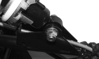
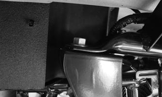
7.Remove the muffler; then remove the final two cap screws securing the rear fascia to the frame.
XR279A
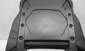
8.From the rear of the vehicle, lift the rear body panel assembly up and toward the rear.
9.To remove the rear storage/rear fascia assembly from the rear body panel, remove the remaining retaining clips from the rear body panel.
XR280A
CLEANING AND INSPECTING 1.Clean all body panel components with warm soap and water. 2.Inspect for cracks. 3.Inspect for missing decals. INSTALLING 1.Secure the rear storage/rear fascia to the rear body panel using the retaining clips.
XR280A
2.Place the rear body panel assembly onto the vehicle.
Secure the bottom of the rear fascia to the frame using the two cap screws; then install the muffler.
XR279A
3.Place the passenger footwells into position. Secure the footwells to the rear body panel using the cap screws and new lock nuts. Secure the footrests onto the footwells.
XR277A
XR278
4.Place the heat shield over the left rear taillight; then secure both taillight assemblies to the rear fascia using the self-tapping screws.
XR241A
5.Guide the threaded studs of the rear rack through the frame; then secure the rack using new lock nuts.
XR276A
6.Secure the two cap screws located behind the PDM.
XR275A
7.Place the steel battery support into the rear panel.
Connect the battery (positive cable first); then install the battery cover.
XR274A
8.Install the side panels, gas tank cap, and seats.
LCD Gauge
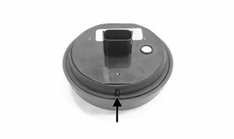
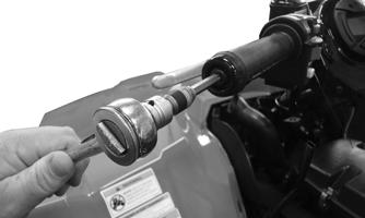
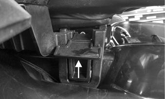
REMOVING/INSTALLING To remove the gauge, pull out on one side of it; then disconnect the multi-pin connector and remove the gauge.
XR283
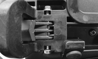
To install the gauge, connect the multi-pin connector and press the gauge into the dash. NOTE: Ensure the rubber mounting ring is oriented correctly on the tab and seats fully through the pod.
WT601A
Steering Post/Tie Rods
REMOVING 1.Remove both seats, storage tray lid, front storage tray, and both side panels. 2.Remove the ignition switch retaining ring; then remove the reinstallable rivets securing the instrument pod to the mounting bracket and remove the pod and LCD gauge.

XR284A
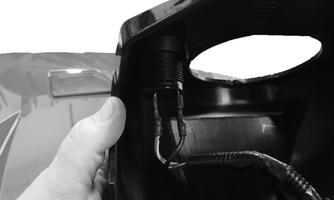
3.Disconnect the accessory plug wires from the pod.
Note the location of each wire.
XR285
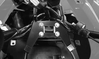
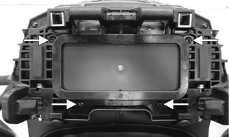
4.Remove the four cap screws securing the two handlebar clamps and LCD gauge bracket to the steering post; then move the handlebar and gauge out of the way. Account for four handlebar cap screws.
XR286
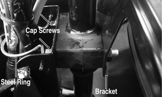
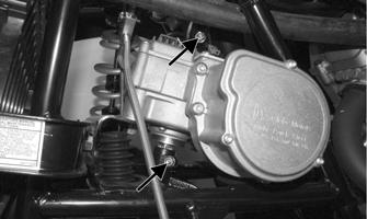
5.Remove the steel ring around the harness; then remove the two cap screws securing the upper steering post bushings to the frame. Account for two housings and steering post rear bracket.
XR287A
6.Using a suitable lift stand, raise the ATV enough to remove the front wheels.
NOTE: For models not equipped with electronic power steering, proceed to step 11. 7.Remove the left front shock absorber; then remove the cap screws and nuts from the steering post to the
EPS couplers.
EPS005A
8.Pull upward on the handlebar to disengage the upper coupler from the EPS assembly. 9.Disconnect the 2-pin and 8-pin connectors from the top of the EPS housing.
EPS007A
10.Remove four cap screws securing the EPS housing to the frame; then lift the assembly upward sufficiently to disengage the lower coupler and remove from the left side.
11.Remove the cotter pins and nuts from the inner and outer tie rod ends; then remove the tie rods from the steering post arm and the left-side and right-side steering knuckles.
CAUTION
Do not attempt to disassemble the EPS assembly as there are no serviceable components within the assembly and damage will occur voiding the EPS warranty.

AF778D

XR288
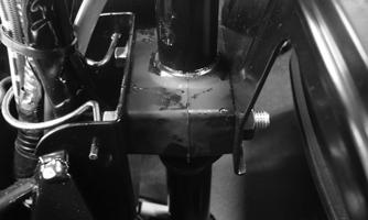
12.Remove two cap screws securing the lower steering post bearing flange to the frame; then remove the steering post.
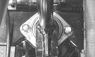
AL600D
CLEANING AND INSPECTING 1.Clean and inspect the pivot area for wear. Apply a low-temperature grease to the ends. ! WARNING
Always wear safety glasses when using compressed air.
2.Inspect the tie rods for damaged threads or wear. 3.Inspect the tie rods for cracks or unusual bends. 4.Inspect all welded areas for cracks or deterioration. 5.Inspect the steering post and steering-post brackets for cracks, bends, or wear. 6.Inspect the bearing halves, bearing caps, and bearing housings for cracks or wear. 7.Inspect the handlebar tube for cracks, wear, or unusual bends. 8.Inspect the handlebar grips for damage or wear. INSTALLING (Models without Electronic Power Steering) 1.Place the steering post into position; then secure the lower bearing flange to the frame with two cap screws. Tighten to 20 ft-lb (27.2 N-m).
AL600D
2.Place the thicker steering post bushing in front of the steering post and the thinner bushing behind it; then insert the two cap screws through the front and thread into the bracket. Tighten to 20 ft-lb (27.2
N-m). 3.Install the steel ring around the harness and into the frame.
XR287
4.Install the tie rods and secure with the new nuts.
Tighten to 30 ft-lb (40.8 N-m); then install new cotter pins.

AF778D
5.Install the front wheels using a crisscross pattern, tighten the wheel nuts in 20 ft-lb (27.2 N-m) increments to a final torque of 40 ft-lb (54.4 N-m) (steel wheel), 60 ft-lb (81.6 N-m) (aluminum wheel w/black nuts), or 80 ft-lb (108.8 N-m) (aluminum wheel w/chrome nuts). 6.Lower the ATV and place the handlebar and caps into position on the steering post; then position the bracket on top of the caps and secure with the four cap screws. Tighten securely. 7.Install the side panels and the storage compartment box; then attach the storage compartment cover assembly by engaging the tabs into the slots and sliding forward. Lock the storage compartment lid to hold the assembly in place. 8.Connect the accessory plug. Place the instrument pod into position; then secure with two reinstallable rivets and the ignition switch retaining ring.
XR284A
INSTALLING (Models with Electronic Power Steering) 1.Place the lower steering post into position; then secure the lower bearing flange to the frame with two cap screws. Tighten to 20 ft-lb (27.2 N-m).
AL600D
2.Making sure the double spline is aligned to the slot in the lower coupler, install the EPS output shaft into the lower coupler; then install the four caps screws securing the EPS housing to the frame. Tighten to 35 ft-lb (47.6 N-m).
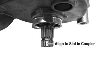
EPS008A EPS007
3.Install the tie rods and secure with the lock nuts.
Tighten to 30 ft-lb (40.8 N-m); then install new cotter pins.
AF778D
4.Connect the 2-pin and 8-pin connectors to the EPS assembly.
EPS007A
5.Align and engage the upper steering post couple to the top of the EPS unit. 6.Install the steel ring around the harness and into the frame. Secure the upper steering post to the frame using the two steering post bushings and rear support plate. Tighten to 20 ft-lb (27.2 N-m).
XR287A
7.Tighten the upper and lower steering post coupler lock nuts and cap screws to 11 ft-lb (15 N-m).
EPS005A
8.Install the side panels, steering post, access cover, storage compartment, and lid; then install the shock absorber and tighten to 50 ft-lb (68 N-m). 9.Install the front wheels using a crisscross pattern, tighten the wheel nuts in 20 ft-lb (27.2 N-m) increments to a final torque of 40 ft-lb (54.4 N-m) (steel wheel), 60 ft-lb (81.6 N-m) (aluminum wheel w/black nuts), or 80 ft-lb (108.8 N-m) (aluminum wheel w/chrome nuts). 10.Lower the ATV and place the handlebar and handlebar clamps into position on the steering post; then position the bracket on top of the caps and secure with the four cap screws. Tighten securely. 11.Connect the accessory plug. Place the instrument pod into position; then secure with two reinstallable rivets and the ignition switch with retaining ring.
XR285
Handlebar Grip
REMOVING 1.Loosen but do not remove the cap screws in the end of the handlebar; then tap lightly on the head of the screw to dislodge the handlebar plug.
XR289
2.Grasp the end and remove the cap screw, plug, and end cap. INSPECTING 1.Inspect the grip for wear, cuts, or cracks. 2.Inspect the grip for deterioration. 3.If a grip is damaged, cut the grip lengthwise using a sharp knife or box cutter; then peel off the grip. INSTALLING NOTE: Before installing a grip, use contact removal spray or alcohol to clean the handlebar of glue residue, oil, or any other contaminant. 1.Apply a liberal amount of Handlebar Grip Adhesive to the inside of a new grip. 2.Slide the grip onto the handlebar until it is fully seated with the smooth part of the grip facing up. 3.Wipe off any excess glue; then secure the grip with the handlebar end-cap.
Throttle Control
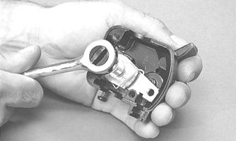
REMOVING 1.Remove the two machine screws securing the throttle control to the handlebar. 2.Slide the grommet out of the lower half of the throttle control; then remove the cable from the actuator arm.
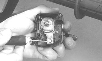
AF676D
3.Remove the cap screw, lock washer, and washer securing the actuator arm to the throttle control lever.
AF677D
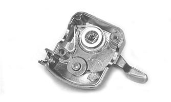
4.Remove the actuator arm and account for a bushing.
Note the position of the return spring for installing purposes.
AF678D
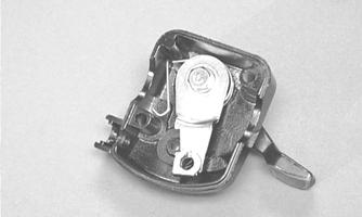
INSTALLING 1.Place the return spring into the throttle control; then place the bushing and actuator arm into position.
Secure with the cap screw, lock washer, and washer.
AF679D
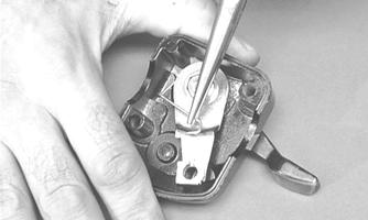
2.Using a pair of needle-nose pliers, place the spring into position on the actuator arm.
AF680D
3.Place the two halves of the throttle control onto the handlebar and secure with the two machine screws. ADJUSTING To adjust throttle cable free-play, see Fuel/Lubrication/Cooling.
Steering Knuckles
REMOVING AND DISASSEMBLING 1.Secure the ATV on a support stand to elevate the wheel; then remove the wheel.
! WARNING
Make sure the ATV is solidly supported on the support stand to avoid injury.
2.Remove the cotter pin from the nut. 3.Remove the nut securing the hub. 4.Remove the brake caliper. NOTE: Do not allow the brake caliper to hang from the cable/hose.
5.Remove the hub assembly. 6.Remove the cotter pin from the tie rod end and remove the tie rod end from the knuckle. 7.Remove the two cap screws securing the ball joints in the knuckle.
8.Tap the ball joint end out of the knuckle; then remove the knuckle. 9.Remove the snap ring from the knuckle; then remove the bearing.
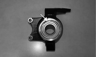
XR166A
CAUTION
Use extreme care when removing the bearing. If the bearing is allowed to fall, it will be damaged and will have to be replaced.
CLEANING AND INSPECTING 1.Clean all knuckle components. 2.Inspect the bearing for pits, gouges, rusting, or premature wear. 3.Inspect the knuckle for cracks, breaks, or porosity. 4.Inspect threads for stripping or damage. ASSEMBLING AND INSTALLING 1.Install the bearing; then install the snap ring making sure it seats into the knuckle.
XR166A
2.Install the knuckle to the upper and lower ball joints and secure with the two cap screws. Tighten to 35 ft-lb (47.6 N-m).
XR290A
3.Install the tie rod end and secure with the nut.
Tighten to 30 ft-lb (40.8 N-m); then install a new cotter pin and spread the pin.
XR288
4.Apply a small amount of grease to the hub splines.
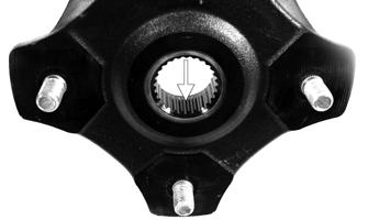
PR290A
5.Install the hub assembly onto the splines of the shaft. 6.Secure the hub assembly with the nut. Tighten only until snug.
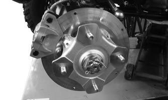
XR291
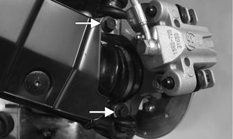
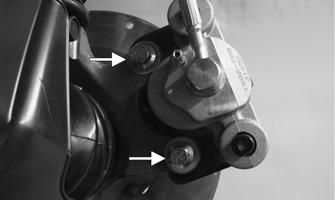
7.Secure the brake caliper to the knuckle with new
“patch-lock” cap screws. Tighten to 20 ft-lb (27.2
N-m).
XR263A
8.Pump the hand brake lever; then engage the brake lever lock. 9.Using an appropriate hub retaining wrench, secure the hub nut (from step 6) to the shaft. Tighten to 200 ft-lb (271 N-m). 10.Install a new cotter pin and spread the pin to secure the nut. 11.Install the wheel; then using a crisscross pattern, tighten the wheel nuts in 20 ft-lb (27.2 N-m) increments to a final torque of 40 ft-lb (54.4 N-m) (steel wheel), 60 ft-lb (81.6 N-m) (aluminum wheel w/black nuts), or 80 ft-lb (108.8 N-m) (aluminum wheel w/chrome nuts). 12.Remove the ATV from the support stand.
Measuring/Adjusting Toe-Out
1.Thoroughly wash the ATV to remove excess weight (mud, etc.). 2.Refer to the specifications and ensure the tires are properly inflated to the recommended pressure. NOTE: Ensure the inflation pressure is correct in the tires or inaccurate measurements can occur.
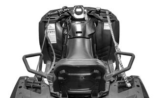
3.Place the ATV in a level position taking care not to push down or lift up on the front end; then turn the handlebar to the straight ahead position. NOTE: When measuring and adjusting, there should be a normal operating load on the ATV (without an operator but with approved accessories). 4.Measure the distance from the outside edge of each handlebar grip to equal reference points on each side of the rear rack.
XR224
5.Adjust the handlebar direction until the two measurements are equal; then secure the handlebar to the rear rack using tie-down straps. NOTE: Care must be taken not to allow the handlebar to turn while securing it. 6.Measure the distance from the inside of each front rim to the bolt securing the front fascia to the front bumper. Repeat for the opposite side.

XR292A
NOTE: The distances from the inside rims to the bolts should be equal. If the measurements are equal, proceed to step 8; if the measurements are not equal, proceed to step 7. 7.To make the measurements equal, loosen the inner and outer tie rod jam nuts and adjust accordingly; then tighten the jam nuts and proceed to step 8.
XR213

AF778D
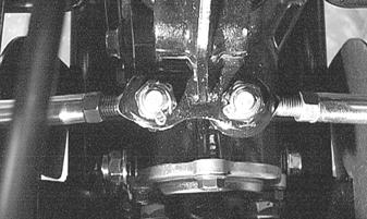
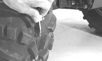
NOTE: The front wheels do not have to be removed to adjust the tie rod. Also, care should be taken not to disturb the handlebar position. 8.Using a permanent marker of some type, mark the center of each front tire (at a height parallel to the belly panel).
AF789D
9.Measure the distance between the marks (at a height parallel to the belly panel) at the front side; then record the measurement. 10.Push the ATV forward until the marks are parallel to the belly panel on the back side; then measure the distance between the marks. 11.The difference in the measurements must show 1/8-1/4 in. toe-out (the front measurement 1/8-1/4 in. more than the rear measurement). 12.If the difference in the measurements is not within specifications, adjust both tie rods equally until within specifications. NOTE: Prior to locking the jam nuts, make sure the ball joints are at the center of their normal range of motion and at the correct angle.
733-559A
Shift Lever
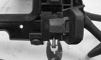
REMOVING 1.Remove the seats, shift lever knob, and left side panel. 2.Remove the E-clip with washer securing the shift lever from the shift rod. Account for the bushing behind the shift linkage.
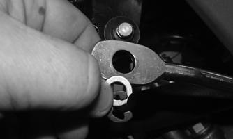
XR294
3.Remove the E-clip securing the shift lever to the shift lever axle.
XR295
INSTALLING 1.Ensure the O-rings are in place on the axle; then secure the shift lever to the arm with a new E-clip and washer.
2.Place the bushing (shouldered side inward) onto the bottom of the shift lever. Position the eyelet of the shift linkage onto the shift lever bushing. Install the washer and a new E-clip to secure. 3.Check shift lever adjustment (see Periodic Maintenance/Tune-up); then tighten jam nut(s) securely. 4.Install the left side panel, shift lever knob, and seat.
Front Bumper
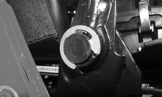
REMOVING NOTE: To remove the front bumper, the front body panel/rack must be removed. Remove the two cap screws and nuts securing the upper tubes of the bumper to the frame.
XR282A
INSTALLING 1.Install the two cap screws and nuts to secure the upper tubes of the bumper to the frame; then tighten to 20 ft-lb (27.2 N-m). 2.Install the front body panel and rack.
Belly Panel
REMOVING/INSTALLING 1.Remove the machine screws securing the belly panel to the underside of the frame; then remove the belly panel. 2.Place the belly panel into position on the underside of the frame; then install the machine screws.
Tighten to 6 ft-lb (8.2 N-m).
Muffler
REMOVING 1.Remove the two exhaust springs at the muffler/exhaust pipe juncture.
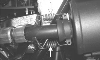
CF138A
2.Slide the muffler rearward to clear the mounting lugs and remove the muffler. INSPECTING 1.Inspect muffler externally for cracks, holes, and dents. 2.Inspect the muffler internally by shaking the muffler back and forth and listening for rattles or loose debris inside the muffler.
NOTE: For additional details on cleaning the muffler/spark arrester, see Periodic Maintenance/Tune-up. INSTALLING 1.Place the muffler into position engaging the mounting lugs into the grommets; then slide the muffler forward. 2.Install the two exhaust springs.
Seat
FRONT
XR254
1.To remove the seat, lift up on the latch release (located at the rear of the seat); then raise the rear of the seat and slide it rearward. 2.Flip the seat over; then, using a pick or small flat blade screwdriver, carefully pry the release tab up.
Slide the latch to the right; then pivot the latch assembly up and out of the seat. Note the orientation of the return spring.

XR373
3.With the return spring installed, slide the latch post into the release tab side of the seat base; then slide the assembly to the left and lock into position. 4.To lock the seat into position, slide the front of the seat into the seat retainers and push down firmly on the rear of seat. The seat should automatically lock into position.
REAR 1.To remove the rear seat, pull the two latch handles upward. ! WARNING
Make sure the seat is secure before mounting the ATV. Severe personal injury may result if the seat is not properly secured.
XR221A
2.Lift the front of the seat up; then pull slightly to the front and lift the seat off the mountings. 3.To remove the passenger seat latches, remove the seat base noting the installed position of the return spring. Flip the seat over and remove the cap screw and lock nut securing the latch to the seat base frame.
XR374A
XR376
4.With the return spring installed into the seat latch, place the latch into the seat base. Guide the cap screw through the seat base, latch, and return spring.
Secure using a new lock nut. 5.Install the seat base and secure using the four cap screws.
XR377
6.To lock the seat into position, engage the two rear mounting lugs into the mounting rack; then push down firmly on the front of the seat to securely lock in place. HANDHOLD 1.Remove the three “patch-lock” cap screws securing the handhold to the seat base.

XR378A
2.Place the handhold onto the seat base; then secure using new “patch-lock” cap screws. SEAT BACK 1.Remove the four shoulder screws securing both seat back posts to the seat base; then remove the six cap screws securing the seat back to the seat back posts.

XR335
XR379
2.With the clip nuts pre-installed into the aluminum seat posts, place the posts into the seat base. Loosely install the four shoulder screws. 3.Slide the seat back onto the posts. Install and secure the six cap screws; then secure the four shoulder screws to the seat base.
! WARNING
Make sure the seat is secure before mounting the ATV. Severe personal injury may result if the seat is not properly secured.
Headlights/Taillights/Brake Lights
REMOVING AND INSTALLING HALOGEN HEADLIGHTS 1.Rotate the back of the headlight bulb counterclockwise, disconnect the wiring harness, and discard the bulb.

XR065C
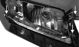
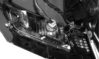
2.Connect the new headlight bulb to the wiring harness and insert into headlight assembly. Turn clockwise to secure the bulb. REMOVING AND INSTALLING LED LIGHT BAR NOTE: The LED light bar is only serviceable as an assembly. 1.Disconnect the wiring harness connectors (A), remove the headlight adjustment screw, and the rubber retaining straps; then remove the headlight assembly.
XR271A
2.Install the new headlight assembly, secure with rubber retaining straps and adjustment screw, and connect the wiring harness connectors. 3.Adjust the headlight (see Checking/Adjusting Headlight Aim in this sub-section.
REMOVING AND INSTALLING TAILLIGHTS/BRAKE LIGHTS NOTE: The taillights/brake lights are only serviceable as an assembly. 1.Disconnect the wiring harness and remove the three screws securing the heat shield (left side only) and taillight; then discard the taillight.
XR241A
NOTE: The heat shield will be removed as an assembly with the left taillight. 2.Insert the taillight into position and secure with existing screws. Tighten securely; then connect the wiring harness. Checking/Adjusting Headlight Aim The headlights can be adjusted vertically. The geometric center of the HIGH beam light zone is to be used for aiming. 1.Position the ATV on a level floor so the headlights are approximately 6.1 m (20 ft) from an aiming surface (wall or similar aiming surface). NOTE: There should be an average operating load on the ATV when adjusting the headlight aim. 2.Measure the distance from the floor to the mid-point of each headlight. 3.Using the measurements obtained in step 2, make horizontal marks on the aiming surface. 4.Make vertical marks which intersect the horizontal marks on the aiming surface directly in front of the headlights. 5.Switch on the lights. Make sure the HIGH beam is on. DO NOT USE LOW BEAM. 6.Observe each headlight beam aim. Proper aim is when the most intense beam is centered on the vertical mark 5 cm (2 in.) below the horizontal mark on the aiming surface. 7.To adjust the headlights, loosen the adjustment knob.
After proper adjustment is achieved, tighten the knob securely.
XR065B
0748-548
Troubleshooting
Problem: Handling too heavy or stiff Condition Remedy
1. Front wheel alignment incorrect 1.Adjust alignment 2. Lubrication inadequate 2.Lubricate appropriate components 3. Tire inflation pressure low 3.Adjust pressure 4. Tie rod ends seizing 4.Replace tie rod ends 5. Linkage connections seizing 5.Repair — replace connections
Problem: Steering oscillation Condition Remedy
1. Tires inflated unequally 1.Adjust pressure 2. Wheel(s) wobbly 2.Replace wheel(s) 3. Wheel hub cap screw(s) loose — missing 3.Tighten — replace cap screws 4. Wheel hub bearing worn — damaged 4.Replace bearing 5. Tie rod ends worn — loose 5.Replace — tighten tie rod ends 6. Tires defective — incorrect 6.Replace tires 7. A-arm bushings damaged 7.Replace bushings 8. Bolts - nuts (frame) loose 8.Tighten bolts — nuts
Problem: Steering pulling to one side Condition Remedy
1. Tires inflated unequally 1.Adjust pressure 2. Front wheel alignment incorrect 2.Adjust alignment 3. Wheel hub bearings worn — broken 3.Replace bearings 4. Frame distorted 4.Repair — replace frame 5. Shock absorber defective 5.Replace shock absorber
Problem: Tire wear rapid or uneven Condition Remedy
1. Wheel hub bearings worn — loose 1.Replace bearings 2. Front wheel alignment incorrect 2.Adjust alignment 3. Tire inflation pressure incorrect 3.Adjust pressure
Problem: Steering noise Condition Remedy
1. Cap screws — nuts loose 1.Tighten cap screws — nuts 2. Wheel hub bearings broken — damaged 2.Replace bearings 3. Lubrication inadequate 3.Lubricate appropriate components 4. Steering shaft bushing or bearing worn 4.Lubricate or replace