11 minute read
Suspension

The following suspension system components should be inspected periodically to ensure proper operation: A.Shock absorber rods not bent, pitted, or damaged. B.Rubber damper not cracked, broken, or missing. C.Shock absorber body not damaged, punctured, or leaking. D.Shock absorber eyelets not broken, bent, or cracked. E.Shock absorber eyelet bushings not worn, deteriorated, cracked, or missing.
F.Shock absorber spring not broken or sagging. SPECIAL TOOL A special tool must be available to the technician when performing service procedures in this section. NOTE: When indicated for use, each special tool will be identified by its specific name, as shown in the chart below, and capitalized.
Description p/n
Spring Tool 0444-224
NOTE: Special tools are available from the Service Department.
Shock Absorbers
REMOVING 1.Secure the ATV on a support stand to elevate the wheels and to release load on the suspension.
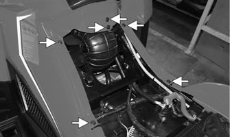
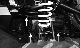
2.Remove the two cap screws and nuts securing each front shock absorber to the frame and the upper
A-arm. Discard the nuts.
! WARNING
Make sure the ATV is solidly supported on the support stand to avoid injury.
CF662 Additional support stands are necessary to support the rear axle when the shock absorbers are removed or damage may occur.
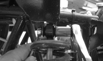
3.Remove the two cap screws and nut securing each rear shock absorber to the frame and lower A-arm.
Account for bushings and sleeves from each.
XR340
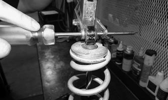
4.Using Spring Tool, compress the shock absorber spring, remove the retainer, and remove the spring.
CF341
CLEANING AND INSPECTING 1.Clean all shock absorber components using a pressure washer. 2.Inspect each shock rod for nicks, pits, rust, bends, and oily residue. 3.Inspect all springs, spring retainers, shock rods, sleeves, bushings, shock bodies, and eyelets for cracks, leaks, and bends. INSTALLING 1.Place the shock absorber spring over the shock absorber, compress the spring, and install the retainer. 2.Install shock with two cap screws and new lock nuts.
Tighten all shock absorber nuts to 50 ft-lb (68 N-m).
CAUTION
Do not tighten the nuts beyond the recommended specification as the shock eyelet or mount WILL be damaged.
REMOVING 1.Secure the ATV on a support stand to elevate the front wheels; then remove the wheels.
2.Remove the cotter pin from the hub nut. Discard the cotter pin. ! WARNING
Make sure the ATV is solidly supported on the support stand to avoid injury.
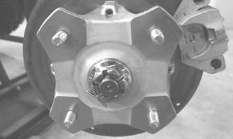
KX041
3.Remove the nut securing the hub. 4.Remove the brake caliper. Account for two cap screws.
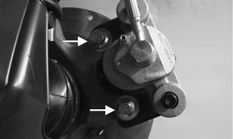
XR263A
NOTE: Do not allow the brake caliper to hang from the cable/hose.
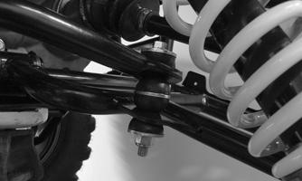
5.Remove the hub assembly. 6.Remove the cotter pin and lock nut securing the tie rod end to the knuckle; then remove the tie rod end from the knuckle.
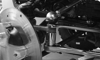
XR367
7.Remove the cap screws securing the ball joints to the knuckle.
CAUTION
Support the knuckle when removing the cap screws or damage to the threads will occur.
XR339B
8.Tap the ball joints out of the knuckle; then remove the knuckle. 9.Remove the lower shock absorber eyelet from the upper A-arm. 10.Remove the cap screws securing the A-arms to the frame.
XR154A
11.Remove the snap ring from the ball joint; then remove the ball joint from the A-arm.
XR368
CLEANING AND INSPECTING 1.Clean all A-arm components using a pressure washer. 2.Clean the ball joint mounting hole of all residual
Loctite, grease, oil, or dirt for installing purposes. 3.Inspect the A-arm for bends, cracks, and worn bushings. 4.Inspect the ball joint mounting holes for cracks or damage. 5.Inspect the frame mounts for signs of damage, wear, or weldment damage. INSTALLING 1.Apply Loctite Primer “T” to the arm socket; then apply green Loctite #609 to the entire outside diameter of the ball joint. Install the ball joint into the
A-arm and secure with the snap ring.
XR368
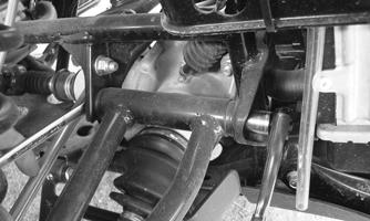
2.Install the A-arm assemblies into the frame mounts using new lock nuts and secure with the cap screws.
Only finger-tighten at this time.
CF661
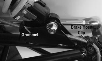
3.Route the brake hose through the upper A-arm shock absorber mount; then secure the hose to the A-arm with the brake hose retainer, and grommet.
XR369A
4.Secure the lower eyelet of the shock absorber to the upper A-arm. Tighten nut to 50 ft-lb (68 N-m). 5.Secure the A-arm assemblies to the frame mounts (from step 2). Tighten the cap screws to 50 ft-lb (68
N-m).
6.Install the knuckle assembly onto the ball joints and secure with cap screws. Tighten to 35 ft-lb (47.6
N-m). CAUTION
Do not tighten the nuts beyond the recommended specification as the shock eyelet or mount WILL be damaged.
XR339B
7.Install the tie rod end and secure with the nut.
Tighten to 30 ft-lb (40.8 N-m); then install a new cotter pin and spread the pin to secure the nut.
XR367
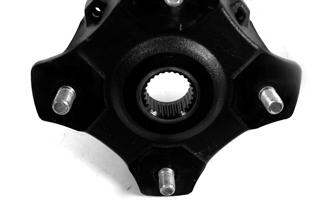
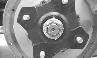
8.Apply grease to the hub and drive axle splines; then install the hub assembly onto the drive axle. 9.Secure the hub assembly to the shaft/axle with the nut. Tighten only until snug at this point. 10.Secure the brake caliper to the knuckle with two new
“patch-lock” cap screws. Tighten to 20 ft-lb (27.2
N-m).
XR263A
11.Tighten the hub nut (from step 9) to 200 ft-lb (271
N-m). NOTE: If the cotter pin does not line up, always tighten to the next alignment. 12.Install a new cotter pin and spread the pin to secure the nut. 13.Install the wheel and tighten the wheel nuts in 20 ft-lb (27.2 N-m) increments to a final torque of 40 ft-lb (54.4 N-m) (steel wheel), 60 ft-lb (81.6 N-m) (aluminum wheel w/black nuts), or 80 ft-lb (108.8
N-m) (aluminum wheel w/chrome nuts). 14.Remove the ATV from the support stand.
REMOVING 1.Secure the ATV on a support stand to elevate the wheels.
2.Pump up the hand brake; then engage the brake lever lock. 3.Remove the wheel. 4.Remove the cotter pin securing the hex nut; then remove the hex nut. Release the brake lever lock. 5.Remove the caliper.
! WARNING
Make sure the ATV is solidly supported on the support stand to avoid injury.
XR370A
NOTE: Do not allow the brake caliper to hang from the cable/hose.
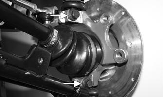
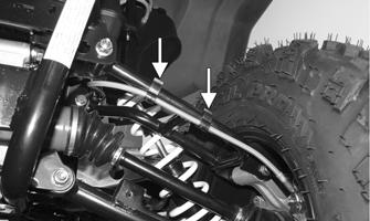
6.Slide the hub off of the drive axle and set aside. 7.Remove the cap screws and lock nuts securing the knuckle to the A-arms. Discard the lock nuts. 8.Remove the cap screws and lock nut securing the shock absorber to the frame and lower A-arm; then remove the shock absorber. 9.Remove the cap screw, lock nut, rubber bushings, and washer securing the sway bar to the lower
A-arm. Note the orientation of the components. NOTE: Never reuse a lock nut. Once a lock nut has been removed, it must be replaced with a new lock nut.
XR371
10.Remove the cap screws and lock nuts securing the
A-arms to the frame; then remove the A-arms. NOTE: If removing the upper right A-arm, it will be necessary to disconnect the brake hose from the A-arm.
CLEANING AND INSPECTING 1.Clean all A-arm components using a pressure washer. 2.Inspect the A-arm for bends, cracks, and worn bushings. 3.Inspect the frame mounts for signs of damage, wear, or weldment damage. INSTALLING 1.Install the A-arm assemblies into the frame and secure with the cap screws and new lock nuts. Only finger-tighten at this time. 2.Slide the knuckle onto the drive axle and into position on the A-arms; then secure the knuckle to the
A-arms with cap screws and new lock nuts. Tighten to 50 ft-lb (68 N-m). 3.Tighten the hardware securing the A-arms to the frame (from step 1) to 50 ft-lb (68 N-m). 4.Apply grease on the drive axle splines; then install the hub assembly onto the drive axle.
PR290
5.Secure the hub assembly with the nut. Tighten only until snug. 6.Secure the brake caliper to the knuckle with two new
“patch-lock” cap screws (right side only). Tighten the caliper to 20 ft-lb (27.2 N-m).
XR412A
7.Compress the hand brake lever and engage the brake lever lock; then tighten the hub nut (from step 5) to 200 ft-lb (271 N-m). 8.Install a new cotter pin and spread the pin to secure the nut.
NOTE: If the cotter pin does not line up, always tighten to the next alignment.
PR260
9.Secure the shock absorber to the frame and A-arm with a cap screw and new lock nut. Tighten to 50 ft-lb (68 N-m). 10.Secure the shock absorber to the lower A-arm with a cap screw. Tighten to 20 ft-lb (27.2 N-m). 11.Secure the sway bar to the lower A-arm using the caps crews, washers, rubber bushings, and new lock nuts. Tighten the lock nuts until 6 threads are showing.
12.Secure the boot guard to the lower A-arm with the two cap screws. Tighten securely. 13.Install the wheel; then using a crisscross pattern, tighten the wheel nuts in 20 ft-lb (27.2 N-m) increments to a final torque of 40 ft-lb (54.4 N-m) (steel wheel), 60 ft-lb (81.6 N-m) (aluminum wheel w/black nuts), or 80 ft-lb (108.8 N-m) (aluminum wheel w/chrome nuts). 14.Remove the ATV from the support stand.
Wheels and Tires
TIRE SIZE
! WARNING
Use only approved tires when replacing tires. Failure to do so could result in unstable ATV operation.
The ATV is equipped with low-pressure tubeless tires of the size and type listed in General Information. Do not under any circumstances substitute tires of a different type or size.
TIRE INFLATION PRESSURE Front and rear tire inflation pressure should be as specified in General Information. REMOVING 1.Secure the ATV on a support stand to elevate the wheels.
2.Remove the wheels. 3.To remove the hub caps, gently press the hub caps out from the back side of the wheel.
! WARNING
Do not mix tire tread patterns. Use the same pattern type on front and rear. Failure to heed warning could cause poor handling qualities of the ATV and could cause excessive drivetrain damage not covered by warranty.
! WARNING
Make sure the ATV is solidly supported on the support stand to avoid injury.
XR372
NOTE: If equipped, the bead lock must be removed before attempting to remove the tire from the rim. NOTE: Keep left-side and right-side wheels separated for installing them on their proper sides. CLEANING AND INSPECTING NOTE: Whenever a part is worn excessively, cracked, or damaged in any way, replacement is necessary. 1.Clean the wheels and hubs using a pressure washer. 2.Inspect each wheel for cracks, dents, or bends. 3.Inspect each tire for cuts, wear, missing lugs, and leaks. INSTALLING 1. Install the wheel; then using a crisscross pattern, tighten the wheel nuts in 20 ft-lb (27.2 N-m) increments to a final torque of 40 ft-lb (54.4 N-m) (steel wheel), 60 ft-lb (81.6 N-m) (aluminum wheel w/black nuts), or 80 ft-lb (108.8 N-m) (aluminum wheel w/chrome nuts). 2.To install the hub caps, press the hub cap into position from the outside of the wheel.
NOTE: Make sure each wheel is installed on its proper hub as noted in removing (the “rotation arrow” (if applicable) must indicate forward direction of rotation). CHECKING/INFLATING 1.Using an air pressure gauge, measure the air pressure in each tire. Adjust the air pressure as necessary to meet the recommended inflation pressure. 2.Inspect the tires for damage, wear, or punctures. ! WARNING
Do not operate the ATV if tire damage exists.
NOTE: Be sure all tires are the specified size and have identical tread pattern. NOTE: If pulling is noted, measure the circumference of the front and rear tires on the pulling side. Compare the measurements with the tires on the opposite side. If pulling is noted during braking only, check and adjust the brakes as necessary and recheck operation (see Periodic Maintenance/Tune-up).
Troubleshooting
Problem: Suspension too soft Condition Remedy
1. Spring(s) weak 1.Replace spring(s) 2. Shock absorber damaged 2.Replace shock absorber 3. Shock absorber preload too low 3.Adjust shock absorber preload
Problem: Suspension too stiff Condition Remedy
1. A-arm-related bushings worn 1.Replace bushing 2. Shock absorber preload too high 2.Adjust shock absorber preload
Problem: Suspension noisy Condition Remedy
1. Cap screws (suspension system) loose 1.Tighten cap screws 2. A-arm-related bushings worn 2.Replace bushings
Problem: Rear wheel oscillation Condition Remedy
1. Rear wheel hub bearings worn — loose 1.Replace bearings 2. Tires defective — incorrect 2.Replace tires 3. Wheel rim distorted 3.Replace rim 4. Wheel hub cap screws loose 4.Tighten cap screws 5. Auxiliary brake adjusted incorrectly 5.Adjust brake 6. Rear suspension arm-related bushing worn 6.Replace bushing 7. Rear shock absorber damaged 7.Replace shock absorber 8. Rear suspension arm nut loose 8.Tighten nut
Problem: Vehicle pulling or steering erratic Condition Remedy
1. Vehicle steering is erratic on dry, level surface 1.Check front wheel alignment and adjust if necessary (see Steering/Body/Controls) 2. Vehicle pulls left or right on dry, level surface 2.Check air pressure in tires and adjust to specifications