Steering/Frame/Controls
3. Remove the cap screws (A); then remove the reinstallable rivets (B) and remove the tank cover.
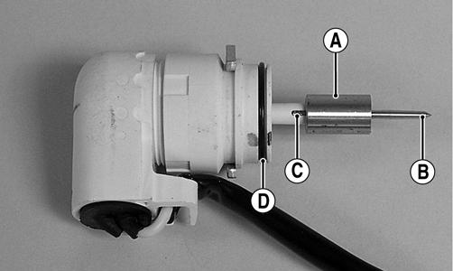
The following steering components should be inspected periodically to ensure safe and proper operation. A. Handlebar grips not worn, broken, or loose. B. Handlebar not bent, cracked, and has equal and complete full-left and full-right capability. C. Steering post bearing assembly/bearing housing not broken, worn, or binding. D. Ball joints not worn, cracked, or damaged. KC219A
E. Tie rods not bent or cracked. F. Knuckles not worn, cracked, or damaged. G. Cotter pins not damaged or missing.
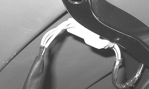
Front Body Panel/Fender REMOVING 1. Remove the seat and both side panels. 2. Remove the front rack; then disconnect the headlight/running light connectors located on the frame.
KC220
4. Remove the shift knob; then remove the shift mechanism splash shield.
KC224
NOTE: Use a small screwdriver to disengage the tab connector allowing the connector assembly to be removed from the frame.
KC223
KC211
5. Remove the screws securing the front body to the front body supports; then remove the left-side and right-side footwell fasteners.
KC204A
17