19 minute read
Periodic Maintenance

This section has been organized into sub-sections which show common maintenance procedures for the Arctic Cat ATV. SPECIAL TOOLS A number of special tools must be available to the technician when performing service procedures in this section. Refer to the current Special Tools Catalog for the appropriate tool description.
Description
Compression Tester Kit Oil Filter Wrench Tachometer Timing Light Valve Clearance Adjuster p/n
0444-213 0644-389 0644-275 0644-296 0444-178
NOTE: Special tools are available from the Arctic Cat Service Department.
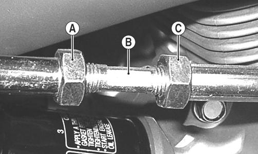
Lubrication Points
It is advisable to lubricate certain components periodically to ensure free movement. Apply light oil to the components using the following list as reference.
A.Throttle Lever Pivot/Cable Ends
B.Brake Lever Pivot/Cable Ends
C.Auxiliary Brake Cable Ends
Air Filter
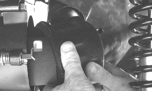
CLEANING AND INSPECTING FILTER 1. Rotate the three locking tabs free of the lugs on the air filter cover; then rotate the cover forward and away from the filter housing.
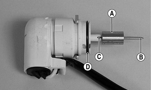
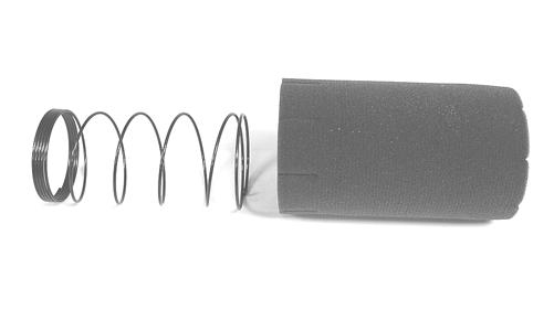
KC0056A KC147 2. Remove the foam filter element from the air filter housing and separate the foam element from the spring.
KC148
KC143 3. Fill a wash pan larger than the element with a non-flammable cleaning solvent; then dip the element in the solvent and wash it.
NOTE: Foam Air Filter Cleaner and Foam Air Filter Oil are available from Arctic Cat.
4. Dry the element.
5. Put the element in a plastic bag; then pour in air filter oil and work the oil into the element. Insert the forming spring into the element with the closely wrapped end of the spring toward the open end of the element.
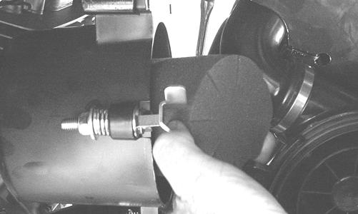
6. Clean any dirt or debris from inside the air cleaner.
Be sure no dirt enters the carburetor. 7. Place the filter assembly in the air filter housing making sure it is properly positioned and properly seated with the filter element straight in the housing.
CAUTION
A torn air filter element can cause damage to the ATV engine. Dirt and dust may get inside the engine if the element is torn. Carefully examine the element for tears before and after cleaning it. Replace the element with a new one if it is torn.
KC147
CAUTION
Failure to properly seat and align the filter element may cause severe engine damage. 8. Install the air filter housing cover and secure with the locking tabs.
KC123
CHECKING AND CLEANING DRAIN 1. Inspect the drain on the filter housing cover and clean out any dirt or debris.
KC0056C 2. Replace any drain that is cracked or shows any signs of hardening or deterioration. 3. Wipe any accumulation of oil or gas from the filter housing and drain.
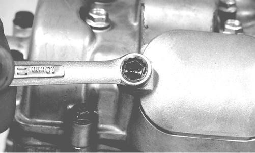
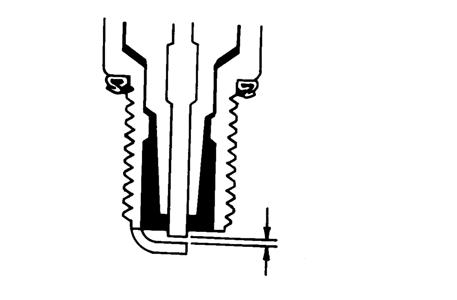
Valve/Tappet Clearance
To check and adjust valve/tappet clearance, use the following procedure. NOTE: The seat, left-side and right-side engine covers, and gas tank must be removed for this procedure.
1. Remove the timing inspection plug and spark plug; then remove the valve inspection covers (for more detailed information, see Engine/Transmission - Servicing Top-Side Components).
CF005 2. Rotate the crankshaft to the TDC position on the compression stroke. NOTE: At this point, the rocker arms and adjuster screws must not have pressure on them.
Feeler Gauge Procedure Using a feeler gauge, check each valve/tappet clearance. If clearance is not within specifications, loosen the jam nut and rotate the tappet adjuster screw until the clearance is within specifications. Tighten each jam nut securely after completing the adjustment.
CAUTION
The feeler gauge must be positioned at the same angle as the valve and valve adjuster for an accurate measurement of clearance. Failure to measure the valve clearance accurately could cause valve component damage. VALVE/TAPPET CLEARANCE
Intake Exhaust 0.076-0.127 mm (0.003-0.005 in.) 0.152-0.203 mm (0.006-0.008 in.)
CC007DC
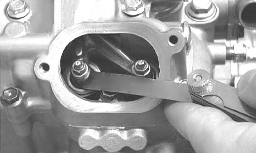
Valve Adjuster Procedure
A.Place the Valve Clearance Adjuster onto the jam nut securing the tappet adjuster screw; then rotate the valve adjuster dial clockwise until the end is seated in the tappet adjuster screw.
B.While holding the valve adjuster dial in place, use the valve adjuster handle and loosen the jam nut; then rotate the tappet adjuster screw clockwise until friction is felt.
C.Align the valve adjuster handle with one of the marks on the valve adjuster dial.
D.While holding the valve adjuster handle in place, rotate the valve adjuster dial counterclockwise until proper valve/tappet clearance is attained. NOTE: Refer to the appropriate specifications in Feeler Gauge Procedure sub-section for the proper valve/tappet clearance.
NOTE: Rotating the valve adjuster dial counterclockwise will open the valve/tappet clearance by 0.05 mm (0.002 in.) per mark.
E.While holding the adjuster dial at the proper clearance setting, tighten the jam nut securely with the valve adjuster handle. 3. Place the two valve inspection covers with O-rings into position; then tighten the covers securely. 4. Install the spark plug; then install the timing inspection plug.
Testing Engine Compression
To test engine compression, use the following procedure. 1. Remove the high tension lead from the spark plug. 2. Using compressed air, blow any debris from around the spark plug. ! WARNING
Always wear safety glasses when using compressed air.
3. Remove the spark plug; then attach the high tension lead to the plug and ground the plug on the cylinder head well away from the spark plug hole. 4. Attach the Compression Tester Kit. NOTE: The engine must be warm and the battery must be fully charged for this test.
5. While holding the throttle lever in the full-open position, crank the engine over with the electric starter until the gauge shows a peak reading of 95-115 psi (five to 10 compression strokes). 6. If compression is abnormally low, inspect the following items.
A.Verify starter cranks engine over at normal speed (approximately 400 RPM).
B.Gauge functioning properly.
C.Throttle lever in the full-open position.
D.Valve/tappet clearance correct.
E.Valve not bent or burned.
F. Valve seat not burned.
NOTE: To service valves, see Engine/Transmission.
7. Pour approximately 30 ml (1 fl oz) of oil into the spark plug hole, reattach the gauge, and retest compression. 8. If compression is now evident, service the piston rings (see Engine/Transmission - Servicing Top Side
Components).
Spark Plug
A light brown insulator indicates that a plug is correct. A white or dark insulator indicates that the engine may need to be serviced or the carburetor may need to be adjusted. To maintain a hot, strong spark, keep the plug free of carbon.
ATV-0051
CAUTION
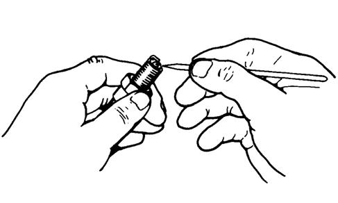
Before removing a spark plug, be sure to clean the area around the spark plug. Dirt could enter engine when removing or installing the spark plug. Adjust the gap to specification (see General Information General Specifications). Use a feeler gauge to check the gap.
ATV0052 When installing the spark plug, be sure to tighten it securely. A new spark plug should be tightened 1/2 turn once the washer contacts the cylinder head. A used spark plug should be tightened 1/8 - 1/4 turn once the washer contacts the cylinder head.
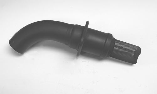
Muffler/Spark Arrester
At the intervals shown in the Periodic Maintenance Chart, clean the spark arrester using the following procedure.
1. Remove the cap screws securing the spark arrester assembly to the muffler; then loosen and remove the arrester. ! WARNING
Wait until the muffler cools to avoid burns.
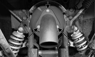
KC334A 2. Using a suitable brush, clean the carbon deposits from the screen taking care not to damage the screen. NOTE: If the screen or gasket is damaged in any way, it must be replaced.
3. Install the spark arrester assembly with gasket; then secure with the cap screws. Tighten to 48 in.-lb.
KC145
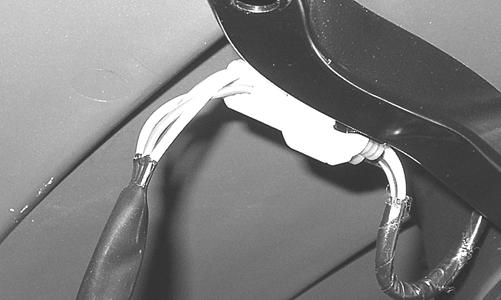
Adjusting Throttle Cable
To adjust the throttle cable free-play, follow this procedure. 1. Slide the rubber boot away; then loosen the jam nut from the throttle cable adjuster.
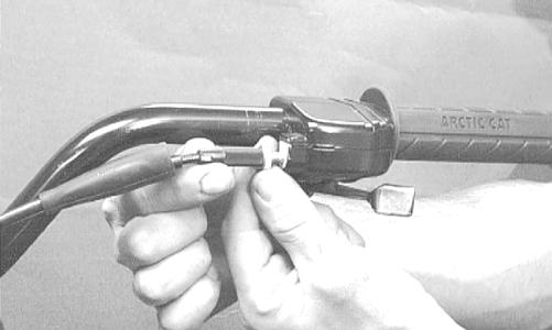
AL611D 2. Turn the adjuster until the throttle cable has proper free-play of 3-6 mm (1/8-1/4 in.) at the lever.
ATV-0047 3. Tighten the jam nut against the throttle cable adjuster securely; then slide the rubber boot over the adjuster.
Adjusting Engine RPM (Idle)
To properly adjust the idle RPM, a tachometer is necessary. To adjust idle RPM, use the following procedure. 1. With the transmission in neutral, start the engine and warm it up to normal operating temperature. 2. Turn the idle adjustment screw clockwise one turn past the recommended RPM setting; then turn it counterclockwise to 1250-1350 RPM.
NOTE: The idle adjustment screw is located under the seat.
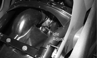
KC356A
! WARNING
Adjust the idle to the correct RPM. Make sure the engine is at normal operating temperature before adjusting the idle RPM.
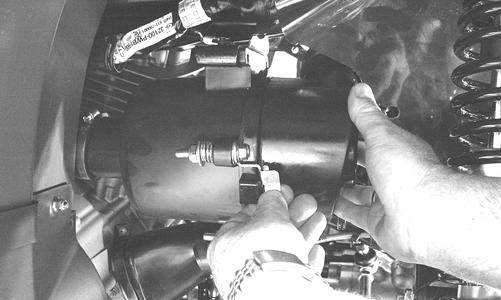
Engine/Transmission Oil - Filter
The engine should always be warm when the oil is changed so the oil will drain easily and completely. 1. Park the ATV on level ground.
KC0051A 4. Remove the drain plug from the bottom of the engine and drain the oil into a drain pan.
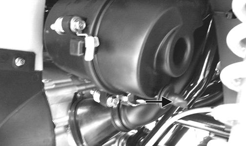
733-441A 5. Remove the oil filter plug from the filter mounting boss (located on the front side of the transmission case) and allow the filter to drain completely. Install the plug and tighten securely. 6. Using the adjustable Oil Filter Wrench and a suitable wrench, remove the old oil filter. NOTE: Clean up any excess oil after removing the filter.
7. Apply oil to a new filter seal ring and check to make sure it is positioned correctly; then install the new oil filter. Tighten securely. 8. Install the engine drain plug and tighten to 20 ft-lb.
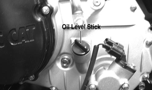
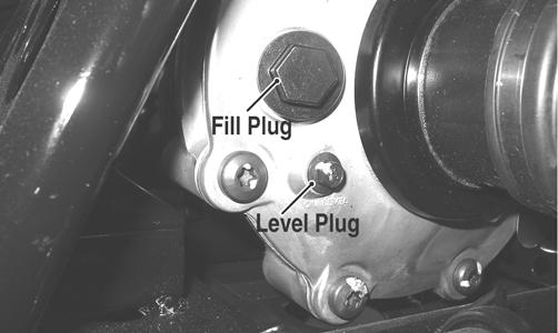
Pour the specified amount of the recommended oil in the filler hole. Install the oil level stick/filler plug.
9. Start the engine (while the ATV is outside on level ground) and allow it to idle for a few minutes. 10. Turn the engine off and wait approximately one minute. CAUTION
Any oil used in place of the recommended oil could cause serious engine damage. Do not use oils which contain graphite or molybdenum additives. These oils can adversely affect clutch operation. Also, not recommended are racing, vegetable, non-detergent, and castor-based oils.
11. Remove the oil level stick and wipe it with a clean cloth; then install the oil level stick into engine case. NOTE: The oil level stick should be threaded into the case for checking purposes.
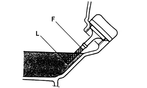
12. Remove the oil level stick; the engine oil level should be above the illustrated “L” mark but not higher than the illustrated “F” mark.
CAUTION
Do not over-fill the engine with oil. Always make sure that the oil level is above the “L” mark but not higher than the “F” mark.
ATV-0100AA 13. Inspect the area around the drain plug and oil filter for leaks. 14. Install the left-side engine cover and the seat.
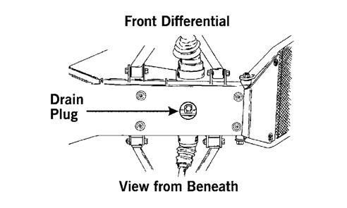
Front Differential/Rear Drive Lubricant
When changing the lubricant, use approved SAE 80W-90 hypoid gear lube. To check lubricant, remove the rear drive filler plug; the lubricant level should be 1 in. below the threads of the plug. If low, add SAE approved 80W-90 hypoid gear lubricant as necessary. To change the lubricant, use the following procedure. 1. Place the ATV on level ground; then remove each fill plug.
ATV0082A
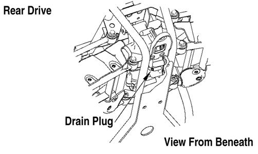
737-651B 3. After all the oil has been drained, install the drain plugs and tighten to 45 in.-lb. 4. Pour the appropriate amount of approved SAE 80W-90 hypoid gear lubricant into the filler hole. 5. Install the fill plugs and tighten to 16 ft-lb. NOTE: If the differential/rear drive oil is contaminated with water, inspect the drain plug, filler plug, and/or bladder.
CAUTION
Water entering the outer end of the axle will not be able to enter the rear drive unless the seals are damaged.
Tires
TIRE SIZES The ATV is equipped with low-pressure tubeless tires of the size and type listed (see General Information - General Specifications). Do not under any circumstances substitute tires of a different type or size. ! WARNING
Always use the size and type of tires specified. Always maintain proper tire inflation pressure.
TIRE INFLATION PRESSURE Front and rear tire inflation pressure should be 27.6 kPa (4.0 psi).
Driveshaft/Coupling
The following drive system components should be inspected periodically to ensure proper operation.
A.Spline lateral movement (slop).
B.Coupling cracked, damaged, or worn.
Nuts/Bolts/Cap Screws
Tighten all nuts, bolts, and cap screws. Make sure rivets holding components together are tight. Replace all loose rivets. Care must be taken that all calibrated nuts, bolts, and cap screws are tightened to specifications.
Ignition Timing
The ignition timing cannot be adjusted; however, verifying ignition timing can aid in troubleshooting other components. To verify ignition timing, use the following procedure. 1. Attach the Timing Light to the spark plug high tension lead; then remove the timing inspection plug from the left-side crankcase cover. 2. Using the Tachometer, start the engine and run at 1500 RPM; ignition timing should be 10° BTDC. 3. Install the timing inspection plug. If ignition timing cannot be verified, the rotor may be damaged, the key may be sheared, the trigger coil bracket may be bent or damaged, or the CDI unit may be faulty.
Shift Lever
CHECKING ADJUSTMENT
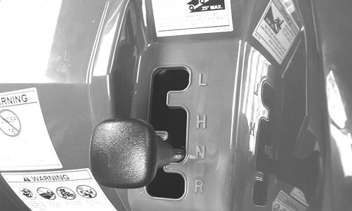
With the engine stopped and the brake lever lock engaged, turn the ignition switch to the ON position; then shift the transmission into each of the gear positions and note that the gear position indicated on the LCD corresponds to the gear position selected by the lever. If the indicator does not correspond to the selected gear, it will be necessary to test drive the ATV to determine if the gear position switch is faulty or the shift lever needs adjustment. If the ATV functions in the gear selected by the shift lever, troubleshoot the gear position switch (see Electrical System). If the ATV functions but the shift lever does not correspond with the gear indicated on the LCD, adjust the shift linkage. To adjust, proceed to ADJUSTING. ADJUSTING 1. Remove the seat; then remove the left-side engine cover. 2. With the ignition switch in the ON position, loosen jam nut (A) (left-hand threads); then loosen jam nut (C) and with the shift lever in the reverse position, adjust the coupler (B) until the transmission is in reverse and the “R” icon appears on the LCD.
KC194A 3. Tighten the jam nuts securely; then shift the transmission to each position and verify correct adjustment. 4. Install the left-side engine cover and seat making sure the seat locks securely in place.
Frame/Welds/Racks
The frame, welds, and racks should be checked periodically for damage, bends, cracks, deterioration, broken components, and missing components. If replacement or repair constitutes removal, see Steering/Frame.
Hydraulic Brake Systems
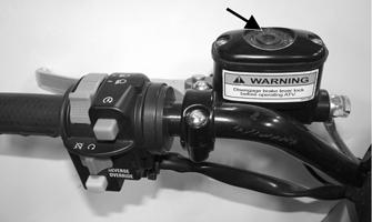
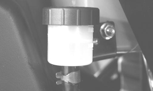
CHECKING/BLEEDING The hydraulic brake systems have been filled and bled at the factory. To check and/or bleed a hydraulic brake system, use the following procedure. 1. With the master cylinder in a level position, check the fluid level in the reservoir. On the hand brake if the level in the reservoir is adequate, the sight glass will appear dark. If the level is low, the sight glass will appear clear. On the auxiliary brake the level must be between the MIN and MAX lines on the reservoir.
CF295A
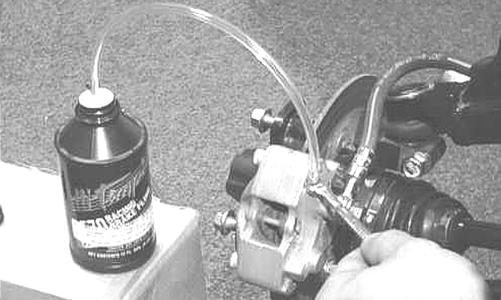
AL681 2. Compress the brake lever/pedal several times to check for a firm brake. If the brake is not firm, the system must be bled. 3. To bleed the brake system, use the following procedure.
A.Remove the cover and fill the reservoir with DOT 4 Brake Fluid.
B.Install and secure the cover; then slowly compress the brake lever/pedal several times.
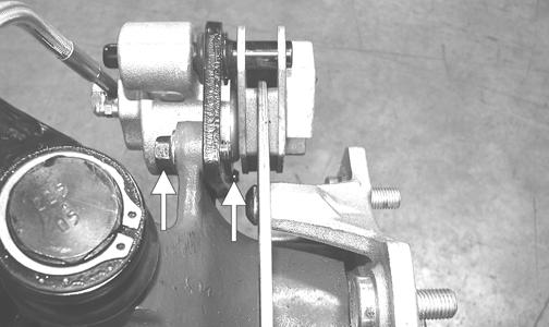
C.Remove the protective cap, install one end of a clear hose onto the REAR RIGHT bleeder screw, and direct the other end into a container; then while holding slight pressure on the brake lever/pedal, open the bleeder screw and watch for air bubbles. Close the bleeder screw before releasing the brake lever/pedal. Repeat this procedure until no air bubbles are present.
AF637D
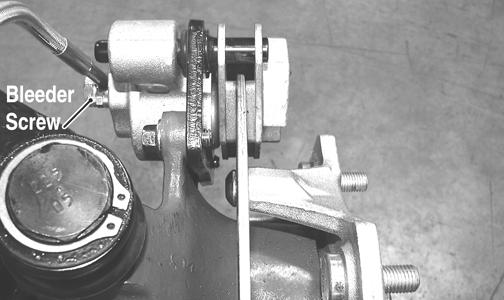
PR377C
NOTE: During the bleeding procedure, watch the appropriate reservoir very closely to make sure there is always a sufficient amount of brake fluid. If low, refill the reservoir before the bleeding procedure is continued. Failure to maintain a sufficient amount of fluid in the reservoir will result in air in the system.
D.Repeat step C until the brake lever/pedal is firm.
E.At this point, perform step B, C, and D on the
FRONT RIGHT bleeder screw; then move to the
FRONT LEFT bleeder screw and follow the same procedure. 4. Carefully check the entire hydraulic brake system that all hose connections are tight, the bleed screws are tight, the protective caps are installed, and no leakage is present.
INSPECTING HOSES Carefully inspect the hydraulic brake hoses for cracks or other damage. If found, the brake hoses must be replaced.
CAUTION
Brake fluid that has been drained or bled from the brake system must NEVER be re-used or severe brake system corrosion and damage may occur. Always discard used brake fluid in an appropriate manner. CAUTION
This hydraulic brake system is designed to use DOT 4 brake fluid only. If brake fluid must be added, care must be taken as brake fluid is very corrosive to painted surfaces.
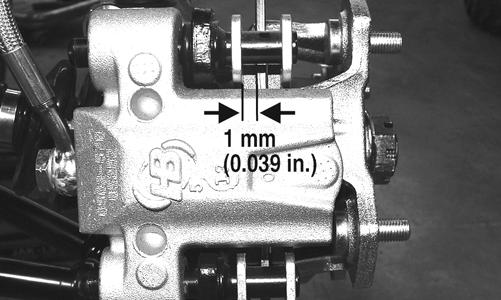
CHECKING/REPLACING PADS The clearance between the brake pads and brake discs is adjusted automatically as the brake pads wear. The only maintenance that is required is replacement of the brake pads when they show excessive wear. Check the thickness of each of the brake pads as follows. 1. Remove a front wheel. 2. Measure the thickness of each brake pad. 3. If thickness of either brake pad is less than 1.0 mm (0.039 in.), the brake pads must be replaced.
PR376B
NOTE: The brake pads should be replaced as a set.
4. To replace the brake pads, use the following procedure.
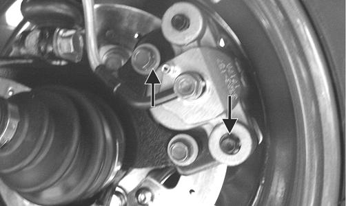
A.Remove the cap screws securing the caliper to the knuckle; then remove the pads.
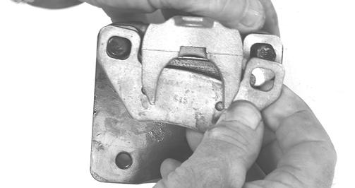
PR237
B.Install the new brake pads. C.Secure the caliper to the knuckle and/or axle housing with new “patch-lock” cap screws.
Tighten to 20 ft-lb.
PR377B 5. Install the wheel. Tighten to 40 ft-lb (steel) or 80 ft-lb (aluminum). 6. Burnish the brake pads.
Burnishing Brake Pads
Brake pads (both main and auxiliary) must be burnished to achieve full braking effectiveness. Braking distance will be extended until brake pads are properly burnished. To properly burnish the brake pads, use the following procedure.
1. Choose an area large enough to safely accelerate the
ATV to 30 mph and to brake to a stop. 2. Accelerate to 30 mph; then compress brake lever or apply the auxiliary brake to decelerate to 0-5 mph. 3. Repeat procedure on each brake system twenty times. 4. Adjust the auxiliary brake (if necessary). 5. Verify that the brakelight illuminates when the hand lever is compressed or the brake pedal is depressed.
! WARNING
Failure to properly burnish the brake pads could lead to premature brake pad wear or brake loss. Brake loss can result in severe injury.
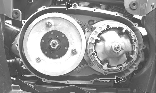
Checking/Replacing V-Belt
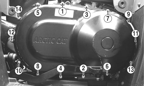
REMOVING 1. Remove the seat and right-side engine cover; then remove the cap screw securing the auxiliary brake pedal to the frame. Account for a flat washer.
KC149A 2. Slide the auxiliary brake pedal part way off the pivot stud but do not remove; then remove the cap screws from the V-belt housing and remove the cover.
Account for two alignment pins and a gasket.
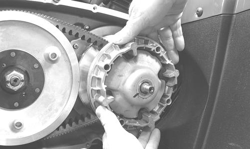
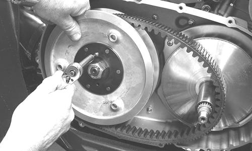
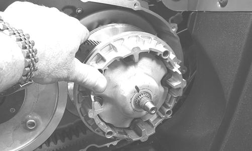
KC142A 3. Remove the nut securing the movable drive face to the clutch shaft; then remove the movable drive face assembly being careful not to let the roller fall out.
Account for a bushing.
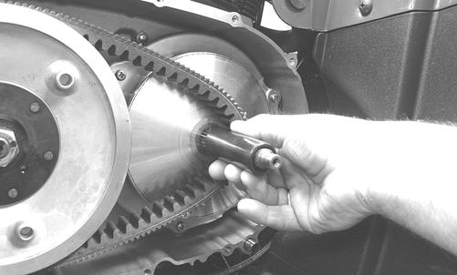
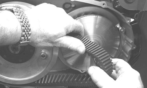
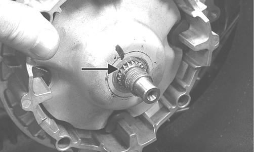
KC127 4. Thread a cap screw from the V-belt cover into the driven pulley fixed face and push the movable face open allowing the V-belt to drop down between the pulley faces approximately 3/4 in.
KC137 5. Pinching the V-belt together in front of the driven pulley, pull it forward and outward off the clutch shaft; then remove it from the driven pulley.
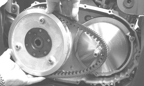
KC136 6. Inspect the faces of the drive and driven pulleys for scoring, pitting, cracks, or grooving; then clean any dirt and debris from the V-belt housing and cover. INSTALLING 1. Place the V-belt onto the driven pulley making sure the arrows point in the direction of rotation; then pinch the belt together in front of the driven pulley and place it over the clutch shaft.
KC135
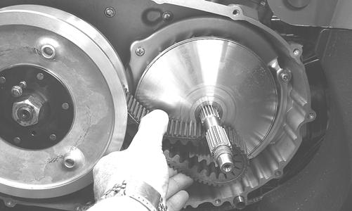
KC131 2. Install the bushing over the clutch shaft; then install the movable drive face assembly on the clutch shaft.
KC128
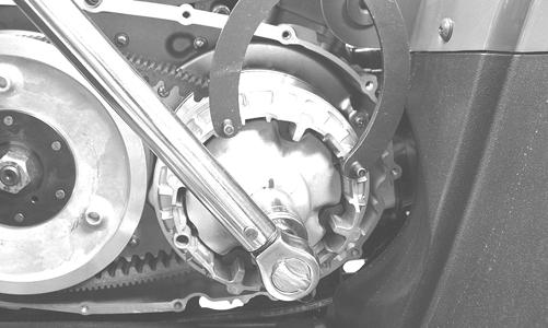
KC138 3. With two drops of red Loctite #271 on the threads and with the splines of the clutch shaft protruding through the movable drive face, install the nut and tighten to 147 ft-lb.
KC141 4. Remove the cap screw from the fixed driven face; then rotate the pulleys counterclockwise until the driven pulley faces are together. 5. With the two alignment pins installed in the V-belt housing and a new V-belt cover gasket in place, install the V-belt cover. Using the pattern shown, secure with the cap screws tightened to 8 ft-lb.
KC142A
KC153A 6. Slide the auxiliary brake pedal fully onto the pivot stud engaging the master cylinder; then secure with the flat washer and cap screw and tighten to 20 ft-lb.