28 minute read
Electrical System

This section has been organized into sub-sections which show procedures for the complete servicing of the Arctic Cat ATV electrical system. The electrical connections should be checked periodically for proper function. In case of an electrical failure, check fuses, connections (for tightness, corrosion, damage), and/or bulbs. SPECIAL TOOLS A number of special tools must be available to the technician when performing service procedures in this section. Refer to the current Special Tools Catalog for the appropriate tool description.
Description
Fluke Model 73 Multimeter Fluke Model 77 Multimeter MaxiClips Peak Voltage Reading Adapter p/n
0644-191 0644-559 0744-041 0644-307
NOTE: Special tools are available from the Arctic Cat Service Department.
TESTING ELECTRICAL COMPONENTS All of the electrical tests should be made using the Fluke Model 73 Multimeter or Fluke Model 77 Multimeter and when testing peak voltage, the Peak Voltage Reading Adapter must be used. If any other type of meter is used, readings may vary due to internal circuitry. When troubleshooting a specific component, always verify first that the fuse(s) are good, that the bulb(s) are good, that the connections are clean and tight, that the battery is fully charged, and that all appropriate switches are activated. NOTE: For absolute accuracy, all tests should be made at room temperature of 68° F.
Battery
The battery is located under the seat. After being in service, batteries require regular cleaning and recharging in order to deliver peak performance and maximum service life. The following procedure is recommended for cleaning and maintaining a sealed battery. Always read and follow instructions provided with battery chargers and battery products. NOTE: Refer to all warnings and cautions provided with the battery or battery maintainer/charger.
Loss of battery charge may be caused by ambient temperature, ignition OFF current draw, corroded terminals, self discharge, frequent start/stops, and short engine run times. Frequent winch usage, snowplowing, extended low RPM operation, short trips, and high amperage accessory usage are also reasons for battery discharge.
NOTE: Arctic Cat recommends the use of the CTEK Multi US 800 or the CTEK Multi US 3300 for battery maintenance charging. Maintenance charging is required on all batteries not used for more than two weeks or as required by battery drain.
800E 1. When charging a battery in the vehicle, be sure the ignition switch is in the OFF position. 2. Clean the battery terminals with a solution of baking soda and water.
NOTE: The sealing strip should NOT be removed and NO fluid should be added.
3. Be sure the charger and battery are in a well-ventilated area. Be sure the charger is unplugged from the 110-volt electrical outlet. 4. Connect the red terminal lead from the charger to the positive terminal of the battery; then connect the black terminal lead of the charger to the negative terminal of the battery. NOTE: Optional battery charging adapters are available from your authorized Arctic Cat dealer to connect directly to your vehicle from the recommended chargers to simplify the maintenance charging process. Check with your authorized Arctic Cat dealer for proper installation of these charging adapter connectors.
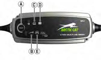
5. Plug the battery charger into a 110-volt electrical outlet. 6. If using the CTEK Multi US 800, there are no further buttons to push. If using the CTEK Multi US 3300, press the Mode button (A) at the left of the charger until the Maintenance Charge Icon (B) at the bottom illuminates. The Normal Charge Indicator (C) should illuminate on the upper portion of the battery charger.
3300A
NOTE: The maintainer/charger will charge the battery to 95% capacity at which time the Maintenance Charge Indicator (D) will illuminate and the maintainer/charger will change to pulse/float maintenance. If the battery falls below 12.9 DC volts, the charger will automatically start again at the first step of the charge sequence.
NOTE: Not using a battery charger with the proper float maintenance will damage the battery if connected over extended periods.
Charging
NOTE: Arctic Cat recommends the use of the CTEK Multi US 800 or the CTEK Multi US 3300 for battery maintenance charging.
1. Be sure the battery and terminals have been cleaned with a baking soda and water solution. NOTE: The sealing strip should NOT be removed and NO fluid should be added.
2. Be sure the charger and battery are in a well-ventilated area. Be sure the charger is unplugged from the 110-volt electrical outlet. 3. Connect the red terminal lead from the charger to the positive terminal of the battery; then connect the black terminal lead of the charger to the negative terminal of the battery. 4. Plug the charger into a 110-volt electrical outlet. 5. By pushing the Mode button (A) on the left side of the charger, select the Normal Charge Icon (E). The
Normal Charge Indicator (C) should illuminate on the upper left portion of the charger. 6. The battery will charge to 95% of its capacity at which time the Maintenance Charge Indicator (D) will illuminate.
NOTE: For optimal charge and performance, leave the charger connected to the battery for a minimum 1 hour after the Maintenance Charge Indicator (D) illuminates. If the battery becomes hot to the touch, stop charging. Resume after it has cooled.
7. Once the battery has reached full charge, unplug the charger from the 110-volt electrical outlet.
NOTE: If, after charging, the battery does not perform to operator expectations, bring the battery to an authorized Arctic Cat dealer for further troubleshooting.
RPM Limiter
NOTE: The ATV is equipped with a CDI unit that retards ignition timing when maximum RPM is approached. When the RPM limiter is activated, it could be misinterpreted as a high-speed misfire.
Accessory Receptacle/Connector
NOTE: This test procedure is for either the receptacle or the connector.
VOLTAGE 1. Turn the ignition switch to the ON position; then set the meter selector to the DC Voltage position. 2. Connect the red tester lead to the red wire; then connect the black tester lead to ground. 3. The meter must show battery voltage. NOTE: If the meter shows no battery voltage, troubleshoot the battery, fuse, receptacle, connector, or the main wiring harness.
Brakelight Switch (Pressure)
The brakelight switch is located on the top of the auxiliary brake master cylinder and is pressure activated by the hand brake or the auxiliary brake pedal. This switch also activates the start-in-gear (SIG) relay in the power distribution module (PDM). NOTE: The ignition switch must be in the ON position.
VOLTAGE (Wiring Harness Side) 1. Set the meter selector to the DC Voltage position. 2. Connect the red tester to the brown/black wire; then connect the black tester lead to ground. 3. The meter must show battery voltage. NOTE: If the meter shows no battery voltage, troubleshoot the battery, fuse, switch, or the main wiring harness.
NOTE: If the meter shows battery voltage, the main wiring harness is good; proceed to test the switch/component or connector.
RESISTANCE (Switch) 1. Remove the spade connectors from the brake switch. 2. Set the meter selector to the OHMS position. 3. Connect the red tester lead to one switch terminal; then connect the black tester lead to the other switch terminal.
KC274 4. When the brake pedal is depressed, the meter must show less than 1 ohm.
NOTE: If the meter shows more than 1 ohm of resistance, replace the switch.
Oil Temperature and Cooling Fan Switches
1. Connect the meter leads (selector in the OHMS position) to the switch contacts. 2. Suspend the switch and a thermometer in a container of cooking oil; then heat the oil. NOTE: Neither the switch nor the thermometer should be allowed to touch the bottom of the container or inaccurate readings will occur. Use wire holders to suspend switch and thermometer.
! WARNING
Wear insulated gloves and safety glasses. Heated oil can cause severe burns. 3. On the oil temperature switch when the oil temperature reaches 160° C (320° F), the meter should read a closed circuit. 4. On the oil temperature switch, allow the oil to cool, and when the temperature is at (or just before) a temperature of 140° C (284° F), the meter should read an open circuit. 5. On the cooling fan switch when the temperature reaches 120° C (248° F), the meter should read a closed circuit. 6. On the cooling fan switch, allow the oil to cool, and when the temperature is at (or just before) a temperature of 110° C (230° F), the meter should read an open circuit. 7. If the readings are not as indicated, the switch must be replaced. 8. Apply thread tape to the threads of the switch; then install the switch and tighten securely. 9. Connect the switch leads.
Fan Motor
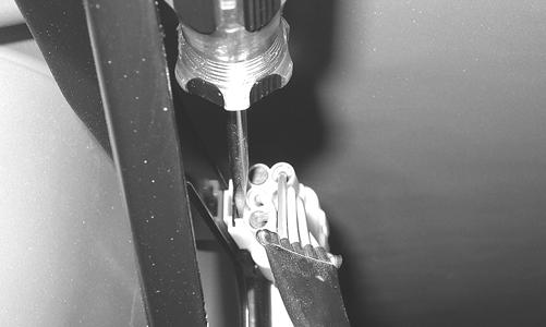
The connector is the black two-prong one located behind the fan assembly along the right-side frame tube.
KC270A
NOTE: The ignition switch must be in the ON position.
VOLTAGE (Main Harness Connector to Fan Motor) 1. Set the meter selector to the DC Voltage position. 2. Connect the red tester lead to the orange wire; then connect the black tester lead to ground. 3. The meter must show battery voltage. NOTE: If the meter shows no battery voltage, troubleshoot the battery, fuse, motor, or the main wiring harness.
NOTE: If the meter shows battery voltage, the main wiring harness is good. The connector should be checked for resistance.
RESISTANCE (Fan Motor Connector) 1. Set the meter selector to the OHMS position. 2. Connect the red tester lead to the red wire; then connect the black tester lead to the black wire. 3. The meter must show less than 1 ohm.
NOTE: If the meter shows more than 1 ohm of resistance, troubleshoot or replace the switch/component, the connector, or the switch wiring harness.
NOTE: To determine if the fan motor is good, connect the blue wire from the fan connector to the positive side of a 12 volt DC power supply; then connect the black wire from the fan connector to the negative side. The fan should operate.
! WARNING
Care should be taken to keep clear of the fan blades.
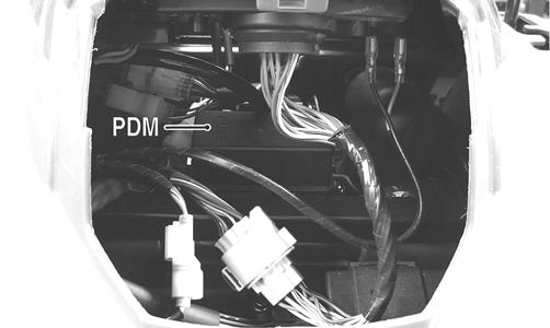
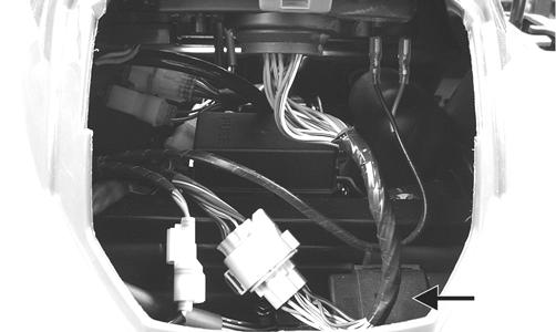
Fuse Block/Power Distribution Module
The fuses are located in a power distribution module in front of the steering post. In addition, there is a 30 amp fuse on the starter relay under the seat next to the battery. If there is any type of electrical system failure, always check the fuses first.
NOTE: To remove a fuse, compress the locking tabs on either side of the fuse case and lift out.
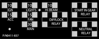
0411-837
CAUTION
Always replace a blown fuse with a fuse of the same type and rating.
KC210A
NOTE: The ignition switch must be in the LIGHTS position.
1. Remove all fuses from the distribution module. 2. Set the meter selector to the DC Voltage position. 3. Connect the black tester lead to ground. 4. Using the red tester lead, contact each end of the fuse holder connector terminals individually. 5. The meter must show battery voltage from one side of the connector terminal ends.
NOTE: Battery voltage will be indicated from only one side of the fuse holder connector terminal; the other side will show no voltage.
NOTE: When testing the HI fuse holder, the headlight dimmer switch must be in the HI position; when testing the LIGHTS fuse holder, the headlight dimmer switch can be in either position.
NOTE: If the meter shows no battery voltage, troubleshoot the battery, switches, distribution module, or the main wiring harness.
CAUTION
Always disconnect the battery when performing resistance tests to avoid damaging the multimeter.
1. Set the meter selector to the OHMS position. 2. Connect the red tester lead to one spade end of the fuse; then connect the black tester lead to the other spade end. 3. The meter must show less than 1 ohm resistance. If the meter reads open, replace the fuse. NOTE: Make sure the fuses are returned to their proper position according to amperage. Refer to the fuse block cover for fuse placement.
RELAYS The relays are identical plug-in type located on the power distribution module. Relay function can be checked by switching relay positions. The relays are interchangeable. NOTE: The module and wiring harness are not a serviceable component and must be replaced as an assembly.
Ignition Coil
The ignition coil is on the frame above the engine. To access the coil, the left side panel must be removed. RESISTANCE
CAUTION
Always disconnect the battery when performing resistance tests to avoid damaging the multimeter. NOTE: For these tests, the meter selector should be set to the OHMS position and the primary wire should be disconnected.
Primary Winding 1. Connect the red tester lead to either terminal; then connect the black tester lead to the other terminal. 2. The meter reading must be within specification. Secondary Winding 1. Remove the plug cap from the high tension lead; then connect the red tester lead to the high tension lead. 2. Connect the black tester lead to ground. 3. The meter reading must be within specification. NOTE: If the meter does not show as specified, replace ignition coil.
Spark Plug Cap 1. Connect the red tester lead to one end of the cap; then connect the black tester lead to the other end of the cap.
AR603D 2. The meter reading must be within specification. NOTE: If the meter does not read as specified, replace the spark plug cap.
PEAK VOLTAGE
NOTE: All of the peak voltage tests should be made using the Fluke Model 73 Multimeter or Fluke Model 77 Multimeter with Peak Voltage Reading Adapter. If any other type of tester is used, readings may vary due to internal circuitry. Primary/CDI
NOTE: The CDI is located on the electrical tray in front of the steering shaft.
KC210B 1. Set the meter selector to the DC Voltage position; then disconnect the black/yellow and black primary wires from the coil.
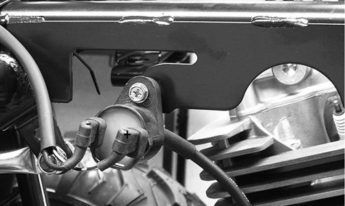
KC229A 2. Connect the red tester lead to the black/yellow wire; then connect the black tester lead to the black wire. 3. Crank the engine over using the electric starter. 4. The meter reading must be within specification.
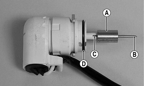
Speed Sensor
1. Set the meter selector to the DC Voltage position. 2. With appropriate needle adapters on the meter leads, connect the red tester lead to the voltage lead (V); then connect the black tester lead to the ground lead (G).
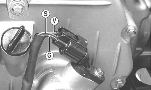
KC248A
3. Turn the ignition switch to the ON position. 4. The meter must show greater than 5.0 volts. 5. Leave the black tester lead connected; then connect the red tester lead to the signal lead pin (S). 6. Slowly move the ATV forward or backward; the meter must show 0 and 6 volts alternately. NOTE: If the sensor tests are within specifications, the speedometer must be replaced (see Steering/Frame/Controls - LCD Gauge).
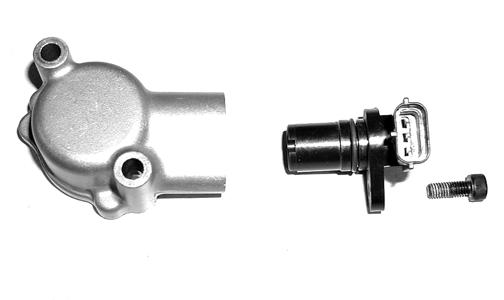
To replace a speed sensor, use the following procedure. 1. Disconnect the three-wire connector from the speed sensor; then remove the cap screw securing the sensor to the sensor housing. 2. Remove the sensor from the sensor housing accounting for an O-ring. 3. Install the new speed sensor into the housing with new O-ring lightly coated with multi-purpose grease; then secure the sensor with the cap screw (threads coated with blue Loctite #242). Tighten securely.
CD071
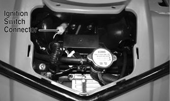
Ignition Switch
The ignition switch harness connects to the switch with a three-pin connector. To access the connector, remove the access panel in front of the handlebar.
KC339D
VOLTAGE
NOTE: Perform this test on the main harness connector.
1. Set the meter selector to the DC Voltage position. 2. Connect the red meter lead to the red/white wire; then connect the black meter lead to ground. 3. Meter must show battery voltage. NOTE: If the meter shows no battery voltage, troubleshoot the battery or the main wiring harness.
RESISTANCE
NOTE: Perform this test on the switch harness using the following procedure.
KC276A
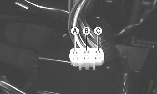
1. Turn the ignition switch to the ON position. 2. Set the meter selector to the OHMS position. 3. Connect either tester lead to pin B; then connect the other tester lead to pin A. 4. The meter must show less than 1 ohm. 5. Turn the ignition switch to the LIGHTS position.
The meter must show less than 1 ohm. 6. Leaving the tester lead on pin B, connect the other tester lead to pin C. 7. The meter must show less than 1 ohm.
NOTE: If the meter shows more than 1 ohm of resistance, replace the switch.
Handlebar Control Switches
The connectors are located on the right side of the ATV next to the PDM. To access the connector, the electrical cover must be removed.
NOTE: These tests should be made on the switch side of the connector.
RESISTANCE (HI Beam) 1. Set the meter selector to the OHMS position. 2. Connect one tester lead to the brown/black wire; then connect the other tester lead to the lavender wire. 3. With the dimmer switch in the HI position, the meter must show less than 1 ohm.
NOTE: If the meter shows more than 1 ohm of resistance, replace the switch.
RESISTANCE (LO Beam) 1. Connect one tester lead to the brown/black wire; then connect the other tester lead to the white wire. 2. With the dimmer switch in the LO position, the meter must show an open circuit. NOTE: If the meter reads resistance, replace the switch.
RESISTANCE (Emergency Stop) 1. Set the meter selector to the OHMS position. 2. Connect the one lead to the brown/lavender wire; then connect the other tester lead to the black/white wire. 3. With the switch in the OFF position, the meter must show an open circuit. 4. With the switch in the RUN position, the meter must show less than 1 ohm.
NOTE: If the meter shows more than 1 ohm of resistance, replace the switch.
RESISTANCE (Reverse Override) 1. Set the meter selector to the OHMS position. 2. Connect one tester lead to one lavender/red wire; then connect the other tester wire to the green/red wire. The meter must show less than 1 ohm. 3. Depress and hold the reverse override button. The meter must show an open circuit. NOTE: If the meter does not show as specified, replace the switch.
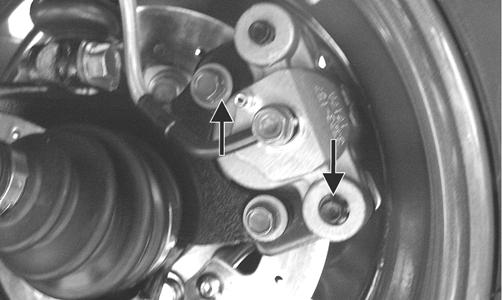
Gear Position Switch
The gear position switch connector is located on the right side of the engine over the V-belt housing.
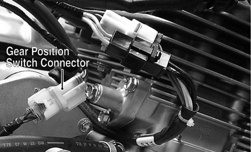
KC227A To troubleshoot the switch, use the following procedure. 1. Disconnect the gear position switch from the main harness at the connector; then connect the black tester lead to a suitable ground. 2. Select the OHMS position on the tester and connect the red tester lead to the lavender/red wire; then move the shift lever to the R (reverse) position. The meter must read less than 1 ohm. 3. Move the red tester lead and shift lever in turn to the light green/red wire and N (neutral) position, white/black wire and H (high) position, and white/red wire and L (low) position. The meter must read less then 1 ohm in all positions. If not, the shift linkage must be adjusted (see Periodic Maintenance -
Shift Lever) or the switch must be replaced.
Stator Coil
VOLTAGE (AC Generator - Regulated Output) 1. Set the meter selector to the DC Voltage position. 2. Connect the red tester lead to the positive battery post; then connect the black tester lead to the negative battery post. 3. With the engine running at a constant 3000 RPM (with the headlights on), the meter must show 14-15.5 DC volts.
CAUTION
Do not run the engine at high RPM for more than 10 seconds.
NOTE: If voltage is lower than specified, test charging coil - no load.
VOLTAGE (Charging Coil - No Load) The connector is the black three-pin one on the right side of the engine just above the starter motor. NOTE: Test the engine-side of the connector.
1. Set the meter selector to the AC Voltage position. 2. Test between the three black wires for a total of three tests. 3. With the engine running at the specified RPM, all wire tests must show 60 AC volts.
CAUTION
Do not run the engine at high RPM for more than 10 seconds.
NOTE: If both charging coil tests failed, check all connections, etc., and test again. If no voltage is present, replace the stator assembly.
RESISTANCE (Charging Coil) 1. Set the meter selector to OHMS position. 2. Test between the three black wires for a total of three tests. 3. The meter reading must be within specification. RESISTANCE (Trigger Coil) 1. Disconnect the gray four-pin connector on the right side of the engine just above the starter motor. 2. Set the meter selector to the OHMS position. 3. Connect the red tester lead to the green/white wire; then connect the black tester lead to the blue/yellow wire. The meter reading must be within specification. PEAK VOLTAGE NOTE: All of the peak voltage tests should be made using the Fluke Model 73 Multimeter or Fluke Model 77 Multimeter with Peak Voltage Reading Adapter. If any other type of tester is used, readings may vary due to internal circuitry.
NOTE: The battery must be at full charge for this test.
Trigger Coil 1. Set the meter selector to the DC Voltage position. 2. Connect the red tester lead to the green wire; then connect the black tester lead to the blue wire. 3. Crank the engine over using the electric starter. 4. The meter reading must be within specification.
Starter Relay
1. Remove the seat; then using the multimeter set to the DC Voltage position, check the relay as follows. 2. Connect the red tester lead to the positive battery terminal; then connect the black tester lead to the starter cable connection on the starter relay. The meter must show battery voltage. NOTE: Make sure that the ignition switch is in the ON position, transmission in neutral, brake lock released, and the emergency stop switch in the RUN position.
3. Depress the starter button while observing the multimeter. The multimeter should drop to 0 volts, a
“click” should be heard from the relay, and the starter motor should run.
NOTE: If a “click” is heard and any voltage is indicated by the multimeter, replace the starter relay. If no “click” is heard and the multimeter continues to indicate battery voltage, test the neutral start relay.
Starter Motor
NOTE: The starter motor is a non-serviceable component. If the following test does not result as specified, the starter motor must be replaced.
TESTING VOLTAGE Perform this test on the starter motor positive terminal. To access the terminal, slide the boot away. NOTE: The ignition switch must be in the ON position, the emergency stop switch in the RUN position, and the shift lever in the NEUTRAL position.
1. Set the meter selector to the DC Voltage position. 2. Connect the red tester lead to the starter terminal; then connect the black tester lead to ground. 3. With the starter button depressed, the meter must show approximately 10.0 DC volts and the starter motor should operate.
AR607D
NOTE: If the meter showed correct voltage but the starter did not operate or operated slowly, the starter motor is defective.
NOTE: If the meter showed no voltage, inspect ground connections, starter motor lead, battery voltage (at the battery), starter relay, or the neutral start relay.
REMOVING 1. Disconnect the battery.
CAUTION
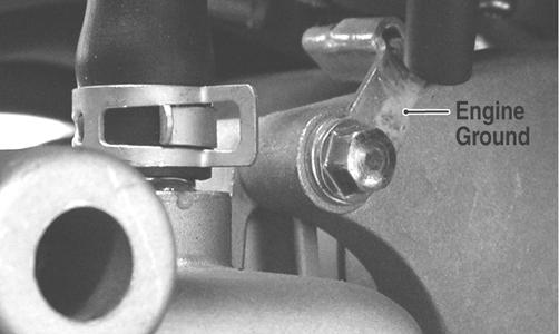
Always disconnect the negative battery cable from the battery first; then disconnect the positive cable. 2. Remove the nut securing the positive cable to the starter; then remove the cable from the starter. 3. Remove the two cap screws securing the starter to the crankcase; then remove the starter. Account for an O-ring. INSTALLING 1. Apply a small amount of grease to the O-ring seal on the starter; then install the starter into the crankcase.
Secure with two cap screws making sure the engine ground is secured by the rear cap screws. Tighten to 8 ft-lb.
KC201A 2. Secure the positive cable to the starter with the nut.
Tighten to 8 ft-lb. 3. Connect the battery.
CDI Unit
NOTE: The CDI unit is not a serviceable component. If the unit is defective, it must be replaced.
The CDI is rarely the cause for electrical problems; however, if the CDI is suspected, substitute another CDI unit to verify the suspected one is defective. NOTE: Prior to replacing the CDI unit to assure the CDI unit is defective, it is advisable to perform a CDI peak voltage test (see Ignition Coil in this section) and/or perform a continuity test of the wiring harness from the CDI connector to the CDI unit.
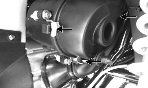
Regulator/Rectifier
The regulator/rectifier is located under the front rack and front fenders above the oil cooler. TESTING 1. Start engine and warm up to normal operating temperatures; then connect a multimeter to the battery as follows. 2. Select the DC Voltage position; then connect the red tester lead to the positive battery post and the black tester lead to the negative battery post. 3. Start the engine and slowly increase RPM. The voltage should increase with the engine RPM to a maximum of 15.5 DC volts.
NOTE: If voltage rises above 15.5 DC volts, the regulator is faulty or a battery connection is loose or corroded. Clean and tighten battery connections or replace the regulator/rectifier. If voltage does not rise, check Voltage (Charging Coil - No Load) in this section. If charging coil voltage is normal, replace the regulator/rectifier.
Lights
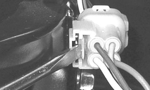
HEADLIGHTS - RUNNING LIGHTS The connectors are the two 4-pin ones snapped onto the front body/rack support. To release the connectors from the frame, press the release tab with a small screwdriver.

KC224
KC223
Voltage (Headlights)
NOTE: Perform this test on the main harness side of the connectors. Also, the ignition switch must be in the LIGHTS position.
1. Set the meter selector to the DC Voltage position. 2. Connect the black tester lead to the black wire; then connect the red tester lead to the white wire. 3. With the dimmer switch in the LO position, the meter must show battery voltage. 4. Remove the red tester lead from the white wire and connect to the lavender wire. 5. With the dimmer switch in the HI position, the meter must show battery voltage. NOTE: If battery voltage is not shown in any test, inspect the fuses, battery, main wiring harness, connectors, or the left handlebar switch.
Voltage (Running Lights) 1. Release the wire connector from the frame; then release and separate the connectors. NOTE: Perform this test on the wiring harness side of the connectors.
2. Connect the black tester lead of the meter to the black wire; then with the tester in the DC Volts position, connect the red tester lead to the brown/black wire. 3. Turn the ignition switch to the LIGHTS position.
The meter must show battery voltage. NOTE: If the meter does not show voltage, inspect the LIGHTS fuse, battery connections, or troubleshoot the main wiring harness.
TAILLIGHTS - BRAKELIGHTS Voltage (Taillights)
NOTE: Perform this test on the main harness side of the connector. Also, the ignition switch should be in the LIGHTS position.
1. Set the meter selector to the DC Voltage position. 2. Connect the black tester lead to the black wire; then connect the red tester lead to the brown/blue wire. 3. The meter must show battery voltage. NOTE: If the meter does not show voltage, inspect fuses, wiring harness, connectors, and switches.
Voltage (Brakelights)
NOTE: Perform this test on the main harness side of the connector. Also, the ignition switch should be in the ON position and the brake (either foot pedal or hand lever) must be applied.
1. Set the meter selector to the DC Voltage position. 2. Connect the black tester lead to the black wire; then connect the red tester lead to the green/yellow wire. 3. The meter must show battery voltage. NOTE: If the meter does not show voltage, inspect bulb, fuses, wiring harness, connectors, and switches.
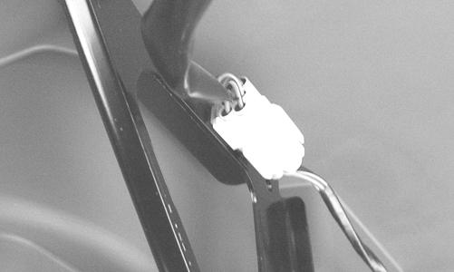
BACK-UP LIGHTS The connectors are located on the rear frame supports attached by a metal tab. They may be released from the frame by depressing the release with a small screwdriver.
KC279
KC280
Voltage 1. Release the wire connectors from the frame; then disconnect the connectors.
NOTE: Perform this test on the main harness side of the connectors.
2. Connect the black tester lead to the brown/lavender wire; then connect the red tester lead to the lavender/red wire.
3. Set the tester to DC VOLTS; then turn the ignition switch to the ON position and move the shift lever to the R (reverse) position. The meter must show battery voltage. NOTE: If the meter does not show battery voltage, use the following procedure to troubleshoot.
4. Remove the black tester lead from the brown/lavender wire and connect to a suitable ground.
A.If the meter shows battery voltage, troubleshoot the gear shift position switch connector or the gear shift position switch. B.If the meter does not show battery voltage, inspect the LIGHTS fuse, ignition switch, or the main wiring harness.
Ignition Timing
The ignition timing cannot be adjusted; however, verifying ignition timing can aid in troubleshooting other components. To verify engine timing, see Periodic Maintenance -Ignition Timing.
Troubleshooting
Problem: Spark absent or weak Condition Remedy 1. Ignition coil defective 1. Replace ignition coil 2. Spark plug defective 2. Replace plug 3. Alternator defective 3. Replace stator coil 4. CDI unit defective 4. Replace CDI unit 5. Pick-up coil defective 5. Replace stator coil Problem: Spark plug fouled with carbon Condition Remedy 1. Gasoline incorrect 1. Change to correct gasoline 2. Air cleaner element dirty 2. Clean element 3. Spark plug incorrect (too cold) 3. Replace plug 4. Valve seals cracked - missing 4. Replace seals 5. Oil rings worn - broken 5. Replace rings 6. Mixture too rich 6. Replace jets with correct size 7. Idling RPM too high 7. Adjust carburetor Problem: Spark plug electrodes overheat or burn Condition Remedy 1. Spark plug incorrect (too hot) 1. Replace plug 2. Engine overheats 2. Service oil filter 3. Spark plug loose 3. Tighten plug 4. Mixture too lean 4. Replace jets with correct size Problem: Alternator does not charge Condition Remedy 1. Stator wires/connections shorted - loose - open 1. Repair - replace - tighten stator wires 2. Stator coils shorted - grounded - open 2. Replace stator coils 3. Regulator/rectifier defective 3. Replace regulator/rectifier Problem: Alternator charges, but charging rate is below the specification Condition Remedy 1. Stator wires shorted - open - loose (at terminals) 1. Repair - tighten Stator wires 2. Stator coils grounded - open 2. Replace stator coils 3. Regulator/rectifier defective 3. Replace regulator/rectifier 4. Battery defective 4. Replace battery 5. Electrolyte low 5. Add distilled water
Problem: Alternator overcharges Condition Remedy 1. Battery shorted 1. Replace battery 2. Regulator/rectifier damaged - defective 2. Replace regulator/rectifier 3. Regulator/rectifier poorly grounded 3. Clean - tighten ground connection Problem: Charging unstable Condition Remedy 1. Stator wire intermittently shorting 1. Replace stator wire 2. Alternator internally shorted 2. Replace stator coil 3. Regulator/rectifier defective 3. Replace regulator/rectifier Problem: Starter button inoperative Condition Remedy 1. Battery charge low 1. Charge - replace battery 2. Switch contacts defective 2. Replace switch 3. Starter motor defective 3. Replace starter motor 4. Starter relay defective 4. Replace relay 5. Emergency stop - ignition switch off 5. Turn on switches 6. Wiring connections loose - disconnected 6. Connect - tighten - repair connections Problem: Battery “sulfation” (Acidic white powdery substance or spots on surfaces of cell plates) Condition Remedy 1. Charging rate too low - too high 1. Repair charging system 2. Battery run-down - damaged 2. Replace battery 3. Electrolyte contaminated 3. Replace battery 4. Battery electrolyte insufficient 4. Keep electrolyte to prescribed level 5. Specific gravity too low 5. Charge battery - add distilled water Problem: Battery discharges too rapidly Condition Remedy 1. Electrolyte contaminated 1. Replace battery 2. Charging system not charging 2. Check alternator - regulator/rectifier - circuit connections 3. Battery overcharged - damaged 3. Replace battery - correct charging system 4. Battery short-circuited 4. Replace battery 5. Specific gravity too low 5. Charge battery - add distilled water Problem: Battery polarity reversed Condition Remedy 1. Battery incorrectly connected 1. Reverse connections - replace battery - repair damage