13 minute read
Fuel/Lubrication/Cooling

NOTE: Arctic Cat recommends the use of new gaskets, lock nuts, and seals and lubricating all internal components when servicing the engine/transmission.
SPECIAL TOOLS A number of special tools must be available to the technician when performing service procedures in this section. Refer to the current Special Tools Catalog for the appropriate tool description.
Description
Electric Choke Test Harness Oil Pressure Test Kit Tachometer p/n
0444-247 0644-495 0644-275
NOTE: Special tools are available from the Arctic Cat Service Department.
Electric Choke
REMOVING 1. Disconnect the electric choke connector from the wiring harness; then remove the screw securing the choke body to the carburetor. 2. Carefully remove the choke assembly from the carburetor taking care not to force the plunger from the carburetor body. INSPECTING/TESTING 1. Inspect the plunger (A) for scoring or scratches, the needle (B) for damage to the tip, the spring (C) for breakage, and the O-ring (D) for breaks.
KC328A 2. With the choke at room temperature (approximately 70° F), measure plunger extension. Measurement (A) should be 18.6-19.1 mm.

KC328B 3. Connect Electric Choke Test Harness to the choke connector and a suitable 12 DC volt power supply for 2-3 minutes. Disconnect the power and measure plunger extension. Measurement (B) should be 22.1-23.4 mm.
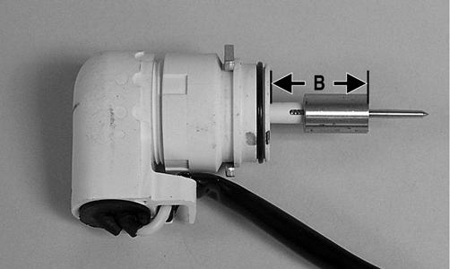
KC328C 4. If the choke is damaged or the measurements are not within specifications, the choke must be replaced. INSTALLING 1. Lightly lubricate the O-ring on the choke body; then carefully insert the choke assembly into the carburetor being careful not to damage the plunger. 2. Secure the choke with the screw and tighten securely; then connect the choke connector to the wiring harness.
Carburetor
KEY 1. Cover 2. Screw 3. Spring 4. Vacuum Piston 5. Spring Seat 6. Jet Needle 7. Needle Jet 8. Jet Holder 9. Main Jet 10. Slow Jet 11. Starter Jet 12. Float Valve 13. Clip 14. Float
15. Float Pin 16. Pilot Screw 17. Spring 18. Washer 19. O-Ring 20. Idle Adjust Screw 21. Washer 22. Spring 23. Plate 24. Screw 25. Electric Choke 26. Choke Cover 27. Float Chamber
Assy 28. O-Ring 29. Screw 30. Spring 31. Diaphragm Assy 32. Pump Housing 33. U-Ring 34. Screw 35. Screw 36. Throttle Cable 37. Cover 38. Screw 39. Vent Hose
! WARNING
0740-600
Whenever any maintenance or inspection is performed on the fuel system during which there may be fuel leakage, there should be no welding, smoking, open flames, etc., in the area.
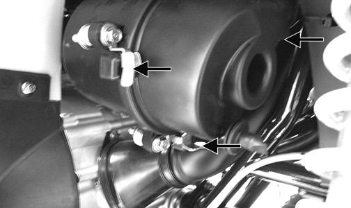
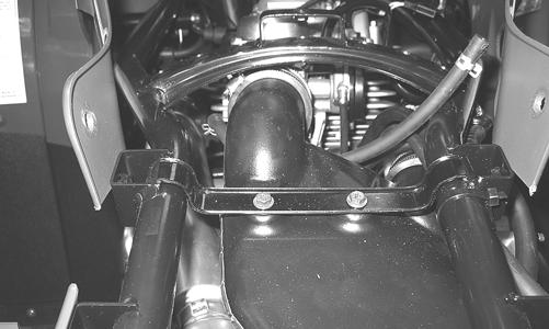
REMOVING 1. Remove the gas tank (see Gas Tank in this section). 2. Disconnect the intake air housing boot from the carburetor; then slide the intake air housing to the rear to clear the carburetor.
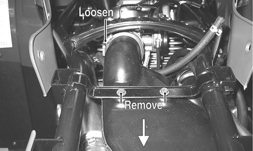
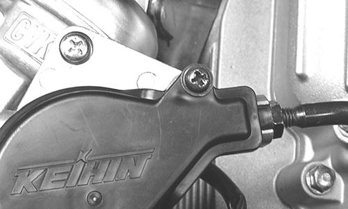
KC257A 3. Loosen the clamp on the intake pipe and lift the carburetor up and to the rear; then disconnect the electric choke connector and vent hose.
KC256A

KC263

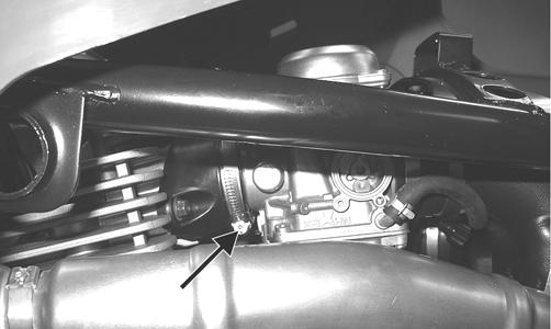
KC264A 4. Remove the throttle arm cover; then loosen the jam nut on the throttle cable and remove the throttle cable from the throttle arm. The carburetor can now be removed for service.

DISASSEMBLING 1. Remove the four Phillips-head screws securing the top cover; then remove the cover.

KC0019A 2. Remove the vacuum piston assembly from the carburetor body. Account for a spring, spring seat, and the jet needle.

KC0021A 3. Remove the three screws securing the pump housing.
Account for the diaphragm assembly, spring, and
U-ring (in the housing).

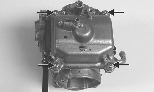
CC748 4. Remove the Phillips-head screws securing the float chamber; then remove the chamber. Account for the
O-ring.
KC0022A

KC0063A
5. Remove the float pin.
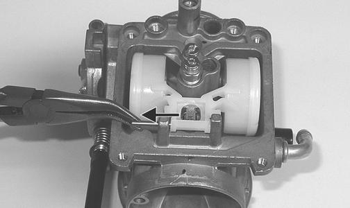
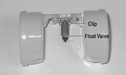
KC0024A 6. Lift the float assembly from the carburetor. Account for the float valve and clip.
KC0025A
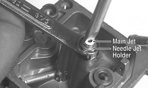
NOTE: Note the locations of the jets, pilot screw, and holder for disassembling procedures.

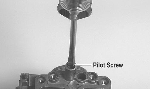
CC761A 7. Secure the needle jet holder with a wrench; then remove the main jet. 8. Remove the needle jet holder; then remove the needle jet, slow jet, and the starter jet. 9. Remove the pilot screw. Account for a spring, washer, and an O-ring.
KC0028A

KC0029A 10. Unscrew and remove the idle adjust screw. Account for the spring and washer.
When drying components with compressed air, always wear safety glasses. CAUTION
DO NOT place any non-metallic components in parts-cleaning solvent because damage or deterioration will result. 1. Place all metallic components in a wire basket and submerge in carburetor cleaner. 2. Soak for 30 minutes; then rinse with clean, hot water. 3. Wash all non-metallic components with soap and water. Rinse thoroughly. 4. Dry all components with compressed air only making sure all holes, orifices, and channels are unobstructed. 5. Inspect the carburetor body for cracks, nicks, stripped threads, and any imperfections in the casting. 6. Inspect the vacuum piston/diaphragm for cracks, imperfections in the casting, or cracks and tears in the rubber. 7. Inspect float for damage. 8. Inspect gasket and O-rings for distortion, tears, or noticeable damage. 9. Inspect tips of the jet needle, pilot screw, and the needle jet for wear, damage, or distortion. 10. Inspect the slow jet and main jet for obstructions or damage. NOTE: If the slow jet is obstructed, the mixture will be extremely lean at idle and part-throttle operation.
11. Inspect the float valve for wear or damage. 12. Inspect the carburetor mounting flange for damage and tightness. ASSEMBLING 1. Thread the idle adjust screw into the carburetor making sure the washer and spring are properly positioned. 2. Install the pilot screw, spring, washer, and O-ring.
KC0028A
NOTE: Turn the pilot screw clockwise until it is lightly seated; then turn it counterclockwise the recommended number of turns as an initial setting.
NOTE: Note the locations of the jets and holder during assembling procedures.
CC761A 3. Install the starter jet and slow jet. Tighten securely.

KC0032A 4. Install the main jet into the needle jet holder and tighten securely; then install the needle jet and needle jet holder assembly into the carburetor and tighten securely.

KC0031
KC0030A 5. Place the float assembly (with float valve) into position and secure to the carburetor with the float pin.

KC0024
NOTE: Check float height by placing the carburetor on its side w/float contacting the needle; then measure with a caliper the height when the float arm is in contact with the needle valve. Float arm height should be 17 mm.

KC0035 6. Place the float chamber into position making sure the
O-ring is properly positioned; then secure with the
Phillips-head screws.
KC0063A
KC0022A 7. Place the U-ring into the pump housing. Position the spring and diaphragm assembly (lip toward the carburetor) onto the carburetor; then secure the assembly with the pump housing and three screws. Tighten securely.
CC748
CAUTION
It is important to press down on the pump housing until it contacts the carburetor to make sure the diaphragm lip is properly seated in the groove in the carburetor. If the diaphragm is not properly seated, leakage will occur.
8. Place the jet needle, spring seat, and spring into the vacuum piston; then place the assembly down into the carburetor.

CC746 9. Place the top cover into position; then secure with the Phillips-head screws. Tighten securely.
KC0019A
INSTALLING 1. Connect the vent hose to the carburetor; then connect the electronic choke connector and install the throttle cable onto the throttle arm.

KC264A
KC263 2. Adjust the throttle cable free-play to specifications (see Periodic Maintenance - Adjusting Throttle
Cable); then tighten the jam nut securely and install the throttle arm cover.
KC258A
KC266 3. Install the carburetor onto the engine making sure the alignment lug on the carburetor is between the two tabs on the air intake pipe; then tighten the clamp securely.
KC245A
KC256A 4. Connect the intake air housing and tighten all clamps and mounting hardware securely.
KC257 5. Install the gas tank (see Gas Tank in this section).
Throttle Cable Free-Play
To adjust throttle cable free-play, see Periodic Maintenance.
Engine RPM (Idle)
Gas Tank
! WARNING
Whenever any maintenance or inspection is made on the fuel system during which there may be fuel leakage, there should be no welding, smoking, open flames, etc., in the area.
REMOVING 1. Turn the fuel shut-off valve to the OFF position; then remove the seat and side panels. 2. Remove the cap screws securing the instrument pod and move it forward.

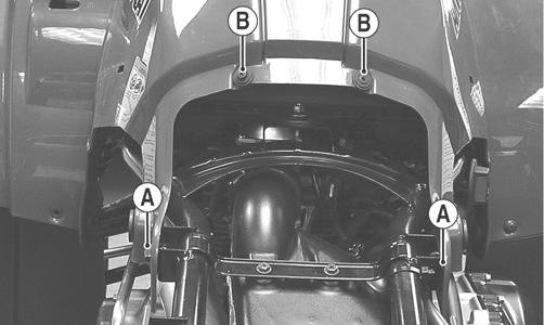
KC507A 3. Remove the cap screws (A) securing the rear of the front body panel to the frame; then remove the two reinstallable rivets (B) securing the gas tank cover to the body.
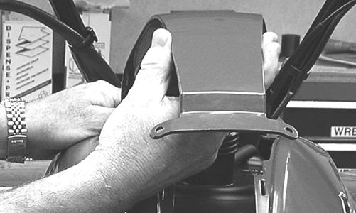
KC219A 4. Remove the gas tank cap; then remove gas tank cover and place the tank cap back on the tank.
KC220 5. Using suitable straps, hook the body panel at the rear of the gas tank and route it over the handlebar to the front rack; then pull it tight to spread open the panel at the rear of the gas tank.
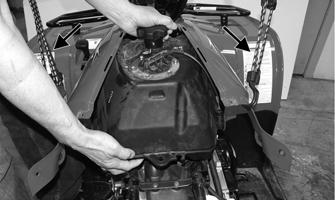
KC509A
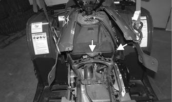
6. Remove the fuel shut-off valve knob.

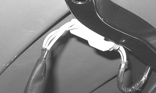
KC515A 7. Remove the cap screw (A) securing the gas tank to the frame; then unplug the fuel level sensor wires (B).
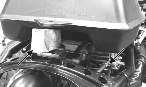
KC514A 8. Using a suitable block, support the rear of the tank; then remove the clamp securing the gasline hose and remove the hose from the fuel shut-off valve.
! WARNING
Gasoline may be under pressure. Place an absorbent towel under the connector to absorb any gasoline spray when disconnecting.
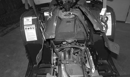
KC241A 9. Remove the gas tank to the rear and account for heat shield. CLEANING AND INSPECTING 1. Clean all gas tank components with parts-cleaning solvent. 2. Inspect all hoses for cracks or leaks. 3. Inspect tank cap and tank for leaks, holes, and damaged threads. INSTALLING 1. Using straps to hold the front plastic open, place the gas tank into position in the frame making sure the heat shield is in position.

KC252A 2. Using a suitable block, support the rear of the tank and connect the gasline hose. Secure with the clamp.
KC241A 3. Remove the block and slide the tank forward, connect the fuel level sensor wires, and insert the cap screw into the rear of tank. Tighten securely.
KC514 4. Remove the straps; then using the existing cap screws, install the instrument pod. Tighten securely. 5. Secure the rear of the front body panel to the frame with the cap screws (A) and tighten securely; then install the gas tank cover and secure with the reinstallable rivets (B).
KC219A 6. Install the fuel shut-off valve knob; then turn the valve to the ON position. 7. Install the side panels and seat making sure they lock securely in place.
Oil Filter/Oil Pump
NOTE: Whenever internal engine components wear excessively or break and whenever oil is contaminated, the oil pump should be replaced. The oil pump is not a serviceable component.
Testing Oil Pump Pressure
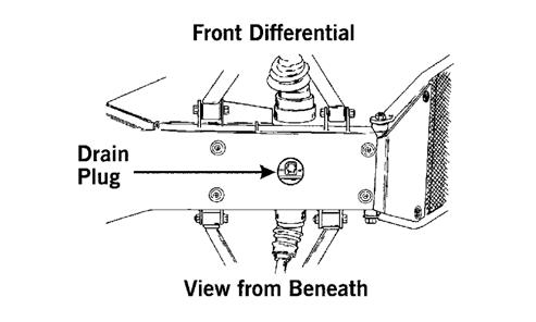
1. Connect the Tachometer to the engine or place the gauge in diagnostic mode and select “tACH.” 2. Connect the Oil Pressure Test Kit to the oil filter drain plug.

KC195A KC267
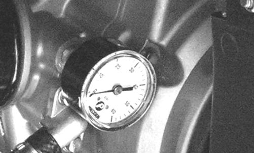
NOTE: Some oil seepage may occur when installing the oil pressure gauge. Wipe up oil residue with a cloth.
3. Warm up the engine to normal operating temperature (cooling fan cycling); then increase engine RPM to 3000 RPM. The oil pressure must read 1.1-1.7 kg/cm2 (16-25 psi).
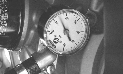
KC268
NOTE: If the oil pressure is lower than specified, check for low oil level, defective oil pump, or restricted oil cooler.
NOTE: If the oil pressure is higher than specified, check for clogged oil passage, clogged oil filter, or improper installation of the oil filter.
Oil Cooler
KEY 1. Oil Cooler Assy 2. Oil Cooler 3. Fan 4. Nut 5. Machine Screw 6. Grommet 7. Shoulder Screw 8. Bushing 9. Clamp 10. Hose 11. Bolt 12. Fitting 13. O-Ring 14. Fitting
0743-004
REMOVING
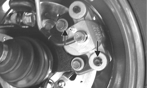
NOTE: It is not necessary to drain the engine oil for this procedure. 2. Remove the cap screws securing the oil cooler to the frame. Account for grommets.
CAUTION
Elevate and secure the hoses to avoid oil spillage.

AL651D
3. Remove the oil cooler from the frame. INSTALLING 1. Place the cooler into position in the frame. 2. Secure the cooler to the frame with the cap screws and grommets. 3. Install the hoses onto their respective fittings and secure with the clamps.
Troubleshooting
Problem: Starting impaired Condition Remedy 1. Starter jet obstructed 1. Clean jet 2. Starter jet passage obstructed 2. Clean passage 3. Carburetor leaking air 3. Replace gasket 4. Gas contaminated 4. Drain gas tank and fill with clean gas Problem: Idling or low speed impaired Condition Remedy 1. Slow jet obstructed - loose 1. Clean - tighten jet 2. Slow jet outlet obstructed 2. Clean outlet 3. Low speed fuel screw setting incorrect 3. Adjust screw 4. Float height incorrect 4. Adjust float height Problem: Medium or high speed impaired Condition Remedy 1. High RPM “cut out” against RPM limiter 1. Shift into higher gear - decrease RPM speed 2. Main jet obstructed 2. Clean main jet 3. Needle jet obstructed 3. Clean needle jet 4. Vacuum piston not operating properly 4. Check piston operation 5. Filter obstructed 5. Clean filter 6. Float height incorrect 6. Adjust float height Problem: Overflow and fuel level fluctuations Condition Remedy 1. Float valve worn - damaged 1. Replace valve 2. Float valve spring broken 2. Replace spring 3. Float not working properly 3. Adjust float height - replace float 4. Float valve dirty 4. Clean valve 5. Float height too high - too low 5. Adjust float height