
4 minute read
Fuel system


2.6 Fuel system
Fuel supply, low-pressure side
The engine is designed to provide optimum performance and fuel consumption if premium unleaded fuel 93 octane ( ) R+M 2 is used. The engine is suitable for operation with fuel containing up to 10% ethanol. The use of fuels containing ethanol can result in increased fuel consumption. If unleaded fuel with 90 octane ( ) or less is used, the engine’s knock control automatically adapts the ignition timing. The use of unleaded fuel with octane numbers of less than 90 octane ( ) could reduce engine power and increase fuel consumption. The vehicle must not be driven at full throttle.
Fig. 2_412_11
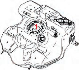
C2 fuel tank, 16.9 gal. (64 liters), 2.6 gal. (10-liter) reserve Carbon canister (not for USA) Installation position of the control unit for the electric fuel pump flow control under the battery retaining bracket.
Special tool 9731 1
The special tool 9731 1 (Fig. 2_413_11) is used for opening the fuel tank cap on the top of the fuel tank (Fig. 2_414_11, 1).
R+M 2
R+M 2
Control unit for electric fuel pump
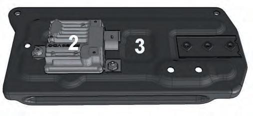
The control unit for electric fuel pump flow control (Fig. 2_416_11, 2) is installed under the battery tray (3). Depending on the amount of fuel required, the current consumption on Carrera 2 vehicles, and thus the delivery rate of the electric fuel pump, is controlled at a level between 6 and 15 amps. The current consumption can be measured at the fuse of the electric fuel pump.

2_416_11 DME engine electronics 2

9731 1
DME engine electronics 2

Returnless fuel system
The 911 Carrera 2 (991) features a returnless fuel system. On the low-pressure side, the electric fuel pump installed in the swirl pot delivers the fuel to the 3-piston high-pressure pump via the fuel filter and fuel pressure regulator (approx. 72.5 psi/ 5 bar).
1 Tank filler neck 2 Surge flap 3 Swirl pot with electric fuel pump 4 Fuel filter with fuel pressure regulator 5 Fuel-level sensor 6 Fill-level control valve 7 Control unit for electric fuel pump 8 Electric lines 9 Low-pressure fuel line (approx. 72.5 psi/5 bar) to high-pressure pump 10 Engine 11 Tank ventilation to carbon canister
The specifications and safety instructions in the PIWIS information system Group 2 must be observed when working on the fuel system.

The procedure for checking the fuel pressure, holding pressure and fuel delivery rate is described in the PIWIS information system Group 2.
2_417_11
Fuel supply, high-pressure side
The fuel high-pressure system is largely the same as that of the previous 997 Carrera model.
Unlike the 997 DFI engines, which are equipped with swirl injectors, the 991 vehicles use six hole injectors with a softer clip.
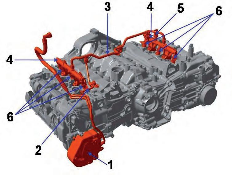
The electric fuel pump in the fuel tank delivers the low-pressure fuel via the quantity control valve (see Fig. 2_419_11, 1.1) at approx. 72.5 psi (5 bar), directly into the 3-piston high-pressure pump (see Fig. 2_418_11, 1). The high-pressure pump driven by the camshaft delivers the fuel high pressure (approx. 580 to 1740 psi/40 to 120 bar) to the fuel rails (4) on the left and right cylinder banks and to the injectors (6) via the connecting lines (3) when the engine is running. The fuel high-pressure sensor (5) is located in the right fuel rail.
1 Fuel high-pressure pump (3 pistons) with quantity control valve (1.1) 2 High-pressure supply line 3 Connecting line (banks 1 and 2) 4 High-pressure rail 5 Fuel high-pressure sensor 6 Injectors (6 holes, with soft clip)
2_418_11 DME engine electronics 2

DME engine electronics 2

2_420_11
2_421_11 Injectors
New fuel injectors with 6 holes are used to ensure more efficient mixture formation, smoother running and maximum power.
Figure 2_420_11 shows a 6 hole injector on the right and a swirl injector on the left.
The 3.4-liter and 3.8-liter engines use injectors with a different injection mass. The engine-specific assignment of the injectors is via the part number as well as a coloured identification clip (see Fig. 2_422_11, 1) on the injector. Figure 2_423_11 shows the 6 hole injector.
2_422_11 2_423_11
Injector holder clip
Fig. 2_421_11:
Using a softer clip to hold the injector dampens the noise made by the injector when closing.
This is necessary because the modified thermodynamics resulting from the 6 hole injectors means that knock detection reacts very sensitively in the rpm range under 3,000 rpm.


