
10 minute read
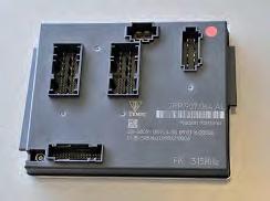
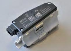
Front-end electronics control unit


9.5 Front-end electronics control unit
The front-end electronics control unit communicates with the gateway via CAN Comfort. The front-end electronics control unit includes several function groups and functions. These will be described in more detail below.

9_44_11
Lighting function group
The side marker lights, dipped beam, high beam and fog lights are controlled by a rotary light switch which is connected to the front-end electronics via a LIN data bus system and a hard-wired connection. The automatic headlights function (rotary light switch position “1”) allows automatic control of light functions by the front-end electrics electronics control unit. This takes place depending on light and weather conditions. A rain-light-moisture sensor is connected via a LIN bus for detection of the prevailing conditions. Other functions such as the headlight flasher and the various direction indicator functions are controlled by the combined steering column module connected to the CAN data bus. The hazard warning light function is activated manually by the hazard warning light button or automatically via a crash signal sent via the CAN data bus (crash flashing). Electrics and electronics 9
Electrics and electronics 9

Other functions/input signals
• Rotary light switch (hard-wired/LIN): redundant cable for LIN failure • Hazard warning light button: activation of the hazard warning light function • Rain-light-moisture sensor: activation of automatic functions (light, wipers, ventilation) • Front lid micro switch: opening the luggage compartment lid
Output signals
• Fog light FL/FR: signal output for fog light activation • Dipped beam FL/FR: high beam FL/FR, signal output for activation of dipped beam/high beam • Side marker light FL/FR: signal output for activation of side marker lights • Direction indicator F/R: signal output for activation of direction indicators (all) • Flasher repeaters: signal output for activation • Drum (AFS) L/R: activation of light functions • Light, front luggage compartment lid: signal output for light activation
Access and driving authorization
The purpose of this function group is to allow a person with a valid key to enter, start and use the vehicle. The system provides a warning by way of audible and visual signals in the event of an unauthorized access attempt. There are two different variants here: 1.) Basic variant with normal radio remote control 2.) Enhanced variant Porsche Entry & Drive
Basic variant
In the basic variant, the radio key (remote control) is used to open, close, lock (radio interface 433 MHz) and start the vehicle (transponder interface).
Porsche Entry & Drive
Porsche Entry & Drive is offered as an option. Porsche Entry & Drive allows vehicle use without active key handling (radio interface for near-field communication 125 kHz) and can be recognized by the lock buttons in the door handles. The system consists of: • Vehicle transmitter inside the vehicle key • System comprising interior and external antennas • Proximity sensors in the door handles and front apron • Locking buttons in the exterior door handles
On vehicles with Porsche Entry & Drive, the vehicle can be unlocked, locked, started and stopped without using the key. The driver simply has to have the key in their possession. As soon as the driver touches the door handle, Porsche Entry & Drive interrogates an access code that is saved in the key.
3 2
3 2 1 1

3 2
9_47_11 Electrics and electronics 9

Deactivation of the radio receiver after a standing time of one week no longer applies.

Electrics and electronics 9

9_49_11
Proximity Sensor 9_50_11 If this is correct, the door is unlocked. In the same way, the luggage compartment lid is released and can be opened if the front end is approached. The vehicle is started or stopped using the operating element (dummy) in the electrical ignition starter switch. To lock the vehicle, one of the locking buttons in one of the door handles or the locking button on the key must be pressed. Porsche Entry & Drive locks the vehicle and activates the steering column lock. If a door or the luggage compartment lid is not completely closed, the vehicle cannot be locked using Entry & Drive. A warning message will then appear on the multi-function display. The key must be outside the vehicle when locking it and within the reception range, otherwise the vehicle doors cannot be locked. If the vehicle key with remote control is out of range, the vehicle doors can no longer be opened after they are locked. To realize this functionality, the electronics of the radio remote control (radio interface 433 MHz) has been extended by the ID transmitter function (radio interface/near-field communication). Proximity sensors were integrated into the outer door handles and external antennas in the area of the front end for keyless access with Porsche Entry & Drive. The system detects the user's intention to access the vehicle by means of these proximity sensors and initiates a coded request via the external antennas. If there is an authorized key on the side on which the intention to access has been detected, this receives the request and returns an appropriate, encoded response to the control unit in the vehicle. Following positive authentication of the key, the function (central locking system) is enabled in accordance with the selected setting. The communication range between the vehicle and key is limited to approx. 5 ft (1.5 m). The key can receive the signal from the external antennas within this range. When leaving the vehicle, the procedure is analogous to that for accessing it. After closing the doors, the user only needs to press one of the locking buttons in the outside door handles to initiate the request to the externally located key. If this request is correctly answered by the key, the vehicle is locked. To start the vehicle, it is sufficient for the key to be inside the vehicle. If the operating element in the ignition lock is actuated, the system initiates a request to the key. If the key is inside the vehicle, it detects the request and returns a specific encoded response. Based on this response, the steering column lock is released electronically, the ignition is activated and the engine is started after positive authentication of the engine immobilizer with the engine control (DME). The engine is switched off by moving the operating element (dummy) into the "off" position. The vehicle can also be locked and unlocked in the conventional way by way of the radio remote control or door locking cylinder.
Online engine immobilizer 5
The electronic engine immobilizer 5 (EI) protects the vehicle from unauthorized use. A 5th generation online engine immobilizer is being used for the 991 Carrera. This function was integrated in the front-end electronics control unit (master). In order to achieve a higher degree of security, the engine immobilizer is distributed over several components. These include: • Vehicle key with transponder • Front-end electronics control unit (FEE) • Electromechanical steering lock (ESL) • Engine control unit (DME) • Alarm system master (rear-end electronics/REE)
Vehicle key with transponder
The vehicle key has a radio interface and a transponder interface. The user can actively operate functions of the central locking system via the radio interface, i.e. lock and unlock the vehicle. A transponder interface is used for the function in the ignition lock (engine start/enabling). The data is exchanged between the key and the ignition lock via this interface. A battery is not required in the key for this interface. With the "Porsche Entry & Drive" option, the key has an additional radio interface for near-field communication/detection of approach to the vehicle (125 kHz). The central locking system (open/close function) responds via the normal radio interface (433 MHz). Electrics and electronics 9 !
The vehicle key includes: Radio interface 433 MHz Transponder interface Porsche Entry & Drive

Electrics and electronics 9

9_53_11
9_54_11
9_55_11

9_56_11 Engine immobilizer 5
The front-end electronics control unit (engine immobilizer master) is responsible for deciding when to release the engine immobilizer. All components of the engine immobilizer must be authenticated by the master (FEE) for this purpose. The engine immobilizer master functionality is integrated in the front-end electronics.
Electromechanical steering lock
The electromechanical steering lock has the task of blocking the steering by mechanical means in order to prevent unauthorized use of the vehicle. The electromechanical steering lock is installed in the steering system and can only be removed after dismantling the steering system. As a component of the electronic engine immobilizer, the electromechanical steering lock must be authenticated for release of the ignition by the engine immobilizer master. When the electromechanical steering lock receives the voltage enable signal from the rear-end electronics, it sends the feedback released/locked to the front-end electronics.
Engine control unit (Digital Motor Electronics - DME)
The engine control unit is authenticated by the engine immobilizer master via the CAN bus. Since the engine immobilizer master and the engine control unit are not on the same CAN bus, the messages are routed via a gateway. The engine management system is released by the engine control unit as a requirement for engine operation only after positive authentication.
Rear-end electronics control unit
After authentication with the engine immobilizer master, the rear-end electronics enables the power supply for the electric steering lock.The alarm system function is integrated into the rear-end electronics (alarm system master). The same processes that are used to release the engine immobilizer are utilized by the rear end control unit. Deactivation of the alarm system takes place using the same encryption as driver authorization and KESSY.
Terminal control function group
The front-end electronics control unit is responsible for terminal control. The relays of terminals 15 and 50HS (High Side) are connected to the control unit for this purpose.Terminal 15: When the ignition is switched on, a relay (main fuse box/power distributor) switches a voltage to terminal 15. Terminal 50HS: A relay switches terminal 50HS if the clutch is pressed (on vehicles with automatic transmission, brake actuated and selector lever in P or N position) and the switch is then set to "Start" position. The DME provides the starter relay with the terminal 50LS (Low Side) activation signal to activate the relay and the engine starts. The switch automatically returns to "ignition" position again from this position. The engine is switched off by turning the ignition lock (electronic ignition lock) to "Off" position. The ignition key is inserted in the ignition lock below the light switch on the left of the steering wheel. On vehicles with Porsche Entry & Drive, it is no longer necessary to insert the key in the ignition lock. Instead, it is sufficient to carry it on your person. The ignition key is replaced by a control unit in the ignition lock that always remains in the ignition lock unless the vehicle is being towed. The ignition lock has three key positions. The ignition lock is connected as a LIN slave with the front-end electronics control unit (LIN master).
Data bus systems
3 LIN data bus systems are connected to the front-end electronics control unit with the following function groups. • LIN 1: Wipers, rotary light switch, rain-light-moisture sensor • LIN 2: Electrically adjustable steering column, Home Link (UGDO) • LIN 3: Electronic ignition lock, electric steering lock Electrics and electronics 9


