1 minute read
Refrigerant circuit


8.4 Refrigerant circuit
The refrigerant circuit is comparable with that of the previous model.
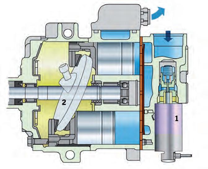
The swash plate adjustable compressor is comparable with the compressor of the current 997 model line in terms of function. It uses an electronic control valve for adjustment (angle of attack) of the swash plate in order to change the stroke (refrigerant delivery rate).
8_22_11 Heating and air conditioning 8

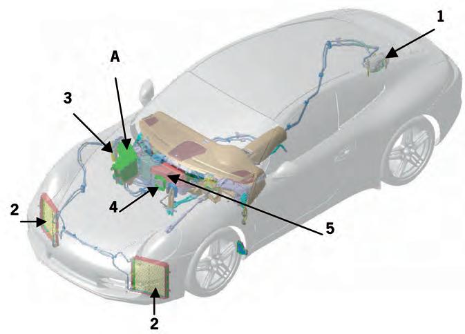
1 Compressor 2 Condenser (left and right) 3 Filter dryer/fluid tank 4 Expansion valve 5 Evaporator A Air intake tube for pre-filter (including air quality sensor)
The air-conditioning compressor (controlled externally) has been taken from the previous model.
1 Electronic control valve 2 Swash plate
The compressor has no magnetic clutch. This means that the compressor is always driven when the engine is running.
Heating and air conditioning 8

The dryer can be accessed for repair work via the right wheel housing –after removal of the wheel housing liner.
1 Filter dryer 2 Pressure sensor
The position of the filter dryer equipment has been changed compared with the previous model. The picture below shows the new position of the dryer. It is located in an opening between the right spring strut mount and the firewall. The pressure sensor is integrated in the refrigerant line on the high-pressure side in the immediate vicinity of the dryer.

8_25_11 1

8_24_11


