Electrical System
Switches
This section has been organized into sub-sections which show procedures for the complete servicing of the Arctic Cat ATV electrical system.
Each time the ATV is used, switches should be checked for proper operation. Use the following list for reference.
SPECIAL TOOLS A number of special tools must be available to the technician when performing service procedures in this section. Refer to the current Special Tools Catalog for the appropriate tool description. Description
p/n
Fluke Model 77 Multimeter
0644-559
MaxiClips
0744-041
Peak Voltage Reading Adapter
0644-307
Tachometer
0644-275
Timing Light
0644-296
A. Ignition switch — engine will start. B. Emergency stop switch — engine will stop. C. Reverse switch — reverse indicator light will illuminate. D. Hi/Lo switch — headlight high beam or low beam will illuminate. E. Brake switches — rear brakelight will illuminate.
Battery
NOTE: Special tools are available from the Arctic Cat Service Parts Department.
RPM Limiter NOTE: The ATV is equipped with a CDI unit that retards ignition timing when maximum RPM is approached. When the RPM limiter is activated, it could be misinterpreted as a high-speed misfire.
Testing Electrical Components
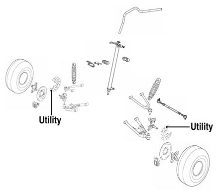
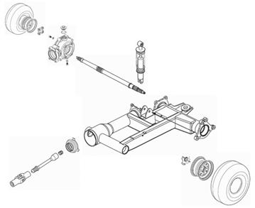
The battery is located under the seat (DVX) or behind the seat (Utility). After being in service, batteries require regular cleaning and recharging in order to deliver peak performance and maximum service life. The following procedure is recommended for cleaning and maintaining a sealed battery. Always read and follow instructions provided with battery chargers and battery products.
! WARNING Any time service is performed on a battery, the following must be observed: keep sparks, open flame, cigarettes, or any other flame away. Always wear safety glasses. Protect skin and clothing when handling a battery. When servicing battery in enclosed space, keep the area well-ventilated.
1. Remove the battery hold-down; then disconnect the battery cables (negative cable first).
All of the electrical tests should be made using the Fluke Model 77 Multimeter and when testing peak voltage, the Peak Voltage Reading Adapter must be used. If any other type of meter is used, readings may vary due to internal circuitry. When troubleshooting a specific component, always verify first that the fuse(s) are good, that the bulb(s) are good, that the connections are clean and tight, that the battery is fully charged, and that all appropriate switches are activated. NOTE: For absolute accuracy, all tests should be made at room temperature of approximately 68° F.
2. Remove the battery from the battery compartment; then thoroughly wash the battery and battery compartment with soap and water. NOTE: If battery posts, cable ends, or the battery case has a build-up of white/green powder residue, apply water and baking soda to neutralize acid; then flush off with warm soapy water.
3. Using a wire brush, clean the battery posts and cable ends removing all corrosive buildup. Replace damaged cables or cable ends.
CAUTION
Electrical Connections The electrical connections should be checked periodically for proper function. In case of an electrical failure, check fuses, connections (for tightness, corrosion, damage), and/or bulbs.
Do not remove seal strip.
! WARNING Battery acid is harmful if it contacts eyes, skin, or clothing. Care must be taken whenever handling a battery.
4. Using a multimeter, test the battery voltage. The meter must read at least 12.5 DC Volts for a fully charged battery. NOTE: At this point if the meter reads as specified, the battery may be returned to service (see step 8).
Manual Table of Contents
73