15 minute read
Fuel/Lubrication/Cooling

Carburetor
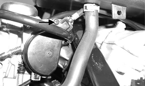
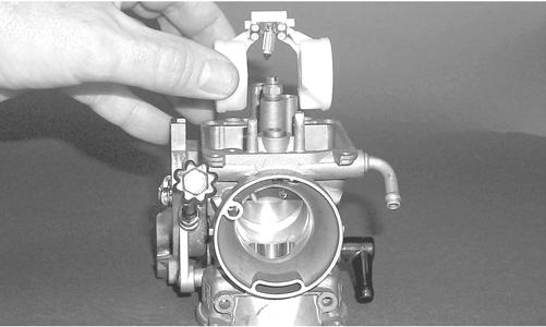
3.Remove the choke assembly from the carburetor leaving the choke cable attached to the choke plunger.
KC0018
4.Remove the screw securing the throttle actuator cover to the carburetor; then remove the cover.
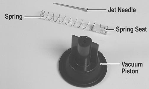
KEY 1.Screw 2.Top 3.Spring 4.Seat, Spring 5.Jet Needle 6.Vacuum Piston 7.Needle Jet 8.Needle Jet Holder 9.Main Jet 10.Starter Valve 11.Coil Spring 12.Cap 13.O-Ring 14.Cable 15.Tube 16.Pilot Screw 17.O-Ring 18.Float Arm Pin 19.Float 20.O-Ring 21.Slow Jet 22.Drain Screw 23.Float Valve 24.Float Valve Clip 25.Float Chamber 26.Screw 27.Clip 28.Drain Tube 29.Spring 30.Washer 31.Washer 32.Spring 33.Idle Adjust Screw 34.Top Cover 35.Screw 36.Starter Jet 0742-556
! WARNING
Whenever any maintenance or inspection is performed on the fuel system during which there may be fuel leakage, there should be no welding, smoking, open flames, etc., in the area.
REMOVING 1.Remove the seat; then remove the gas tank (see Gas
Tank in this section). 2.Remove the cap screws securing the air filter housing to the frame; then loosen the clamp securing air inlet boot to the carburetor and remove the air filter.
PR154B
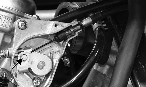
5.Remove the throttle cable from the actuator arm.
PR162C
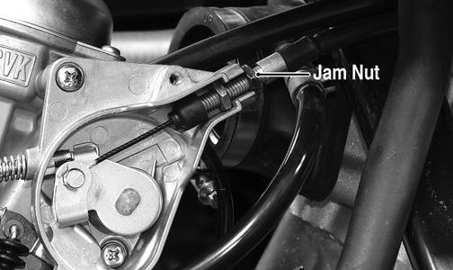
6.Loosen the outer jam nut securing the throttle cable to the carburetor body; then route the cable out of the way.
PR162B
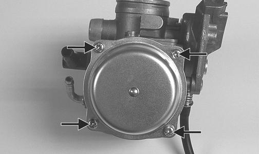
7.Disconnect the vent hose; then remove the carburetor. DISASSEMBLING 1.Remove the four Phillips-head screws securing the top cover; then remove the cover.
KC0019A
2.Remove the vacuum piston assembly from the carburetor body. Account for a spring, spring seat, and the jet needle.
KC0021A
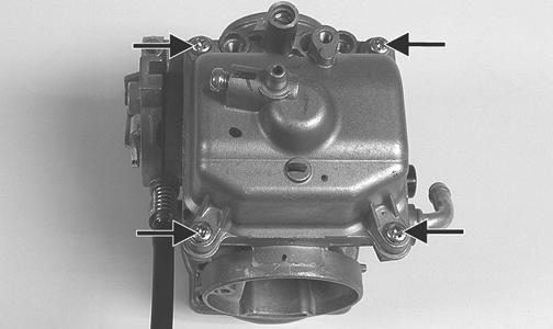
3.Remove the Phillips-head screws securing the float chamber; then remove the chamber. Account for the
O-ring.
KC0022A
KC0063A
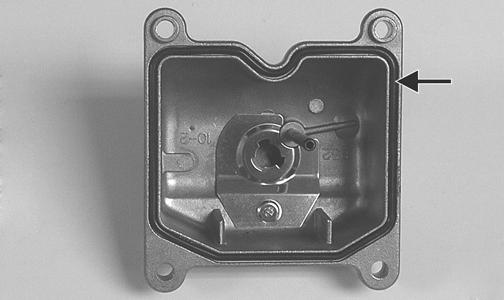
4.Remove the float pin.
KC0024A
5.Lift the float assembly from the carburetor. Account for the float valve.
CC753
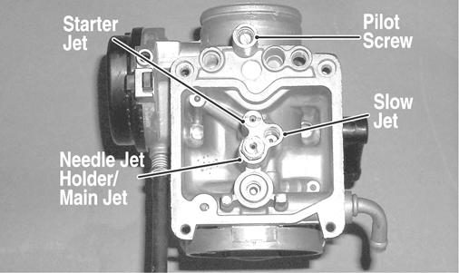
NOTE: Note the locations of the jets, pilot screw,
and holder for disassembling procedures.
CC761A
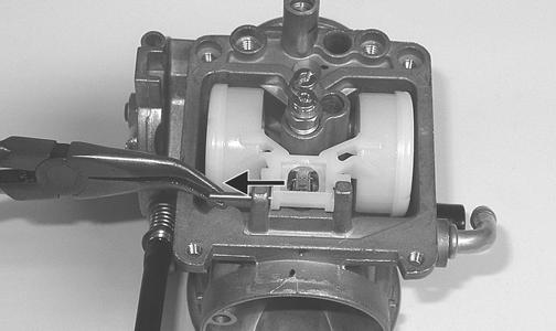
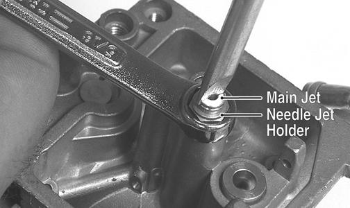
6.Secure the needle jet holder with a wrench; then remove the main jet.
KC0030A
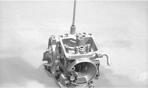
7.Remove the needle jet holder; then remove the needle jet, slow jet, and the starter jet. 8.Remove the pilot screw. Account for a spring, washer, and an O-ring.
CC758
CLEANING AND INSPECTING
NOTE: Whenever a part is worn excessively,
cracked, or damaged in any way, replacement is necessary.
! WARNING
When drying components with compressed air, always wear safety glasses.
CAUTION
DO NOT place any non-metallic components in partscleaning solvent because damage or deterioration will result.
1.Place all metallic components in a wire basket and submerge in carburetor cleaner. 2.Soak for 30 minutes; then rinse with clean, hot water. 3.Wash all non-metallic components with soap and water. Rinse thoroughly. 4.Dry all components with compressed air only making sure all holes, orifices, and channels are unobstructed. 5.Inspect the carburetor body for cracks, nicks, stripped threads, and any imperfections in the casting. 6.Inspect the vacuum piston for cracks, imperfections in the casting, or cracks and tears in the rubber. 7.Inspect float for damage. 8.Inspect gasket and O-rings for distortion, tears, or noticeable damage. 9.Inspect tips of the jet needle, pilot screw, and the needle jet for wear, damage, or distortion. 10.Inspect the slow jet and main jet for obstructions or damage. NOTE: If the slow jet is obstructed, the mixture will
be extremely lean at idle and part-throttle operation.
11.Inspect the float valve for wear or damage. 12.Inspect the carburetor mounting flange for damage and tightness. ASSEMBLING 1.Install the pilot screw, spring, washer, and O-ring.
CC758
NOTE: Turn the pilot screw clockwise until it is
lightly seated; then turn it counterclockwise the recommended number of turns as an initial setting.
NOTE: Note the locations of the jets and holder dur-
ing assembling procedures.
CC761A
2.Install the slow jet. Tighten securely. 3.Install the main jet into the needle jet holder and tighten securely; then install the needle jet, starter jet, and needle jet holder assembly into the carburetor and tighten securely. 4.Place the float assembly (with float valve) into position and secure to the carburetor with the float pin.
CC753
NOTE: Check float arm height by placing the carbu-
retor on its side w/float contacting the needle; then measure with a caliper the height when the float arm is in contact with the needle valve. Float arm height should be 17 mm.
5.Place the float chamber into position making sure the
O-ring is properly positioned; then secure with the
Phillips-head screws.
KC0063A KC0022A
6.Place the jet needle, spring seat, and spring into the vacuum piston; then place the assembly down into the carburetor. 7.Place the top cover into position; then secure with the Phillips-head screws. Tighten securely.
KC0019A
INSTALLING 1.Connect the vent hose onto the carburetor. 2.Place the throttle cable into position and secure by tightening the outer jam nut.
PR162B
3.Connect the throttle cable to the actuator arm.
PR162C
4.Place the throttle actuator cover into position on the carburetor; then secure with the screw.
PR154B
5.Connect the choke assembly to the carburetor. 6.Install the air filter; then tighten the clamp securing the air inlet boot to the carburetor. Secure the air filter housing to the frame with the cap screws. 7.Install the gas tank; then install the seat.
ATV-0047B
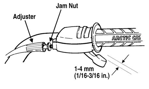
3.Tighten the jam nut against the throttle cable adjuster securely; then slide the rubber boot over the adjuster.
Engine RPM (Idle)
To properly adjust the idle RPM, a tachometer is necessary. To adjust idle RPM, use the following procedure. NOTE: The idle adjustment screw is located on the
right side of the carburetor.
1.With the transmission in neutral, start the engine and warm it up to normal operating temperature. 2.Turn the idle adjustment screw clockwise one turn past the recommended RPM setting; then turn it counterclockwise to the correct setting of 1250-1350
RPM.
! WARNING
Adjust the idle to the correct RPM. Make sure the engine is at normal operating temperature before adjusting the idle RPM.
Throttle Cable Free-Play Gas Tank
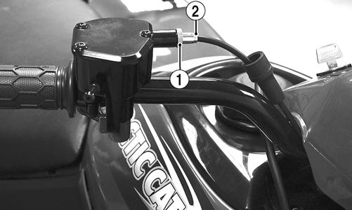
To adjust throttle cable free-play, use the following procedure. 1.Slide the rubber boot away from the adjuster; then loosen the jam nut (1) from the throttle cable adjuster (2).
KM111A
2.Turn the adjuster until the throttle cable has proper free-play of 1-4 mm (1/16-3/16 in.) at the lever. ! WARNING
Whenever any maintenance or inspection is made on the fuel system during which there may be fuel leakage, there should be no welding, smoking, open flames, etc., in the area.
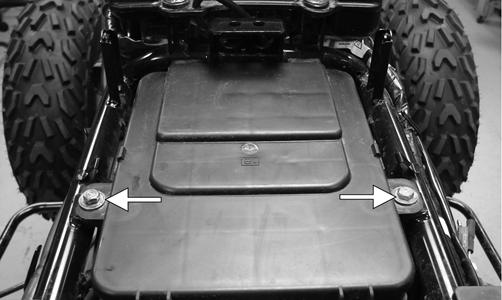
REMOVING 1.Turn the gas tank valve to the OFF position. 2.Remove the seat. 3.Disconnect the hose from the carburetor to the gas tank at the tank connection. 4.Cut the tie-down securing the gas hose to the cables and hoses. 5.Remove the cap screws securing the gas tank to the frame.
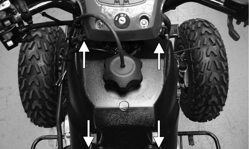
KM327A
6.Remove the vent hose; then remove the gas tank. CLEANING AND INSPECTING NOTE: Whenever a part is worn excessively, cracked,
or damaged in any way, replacement is necessary.
1.Clean all gas tank components with parts-cleaning solvent. 2.Inspect all hoses for cracks or leaks. 3.Inspect gas tank valve, tank cap, and tank for leaks, holes, and damaged threads. 4.Inspect the gas gauge for proper operation. INSTALLING 1.Place the gas tank into position on the frame; then install the cap screws. Tighten securely. 2.Connect the gas hose from the carburetor; then secure hose to cables and hoses with a cable tie. 3.Install the vent hose; then fill the gas tank with gasoline. 4.Turn the gas tank valve to the ON position and inspect for leakage. 5.Install the seat.
Gas Tank Valve
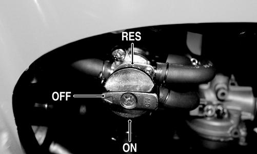
The ATV has a valve attached to the gas tank. There are three positions: ON, RES, and OFF.
KM043A
In the OFF position, the valve will not allow gasoline to flow to the carburetor. In the ON position (the normal operating position), gasoline will flow from the tank to the carburetor. In this position, 4.54 L (1.2 U.S. gal.) will remain in the tank as a reserve quantity. Moving the valve to the RES position will allow the operator to use the remaining gasoline in the tank. When turning the valve to any of the three positions, make sure the indicator is pointed directly at the position desired. REMOVING/INSPECTING ! WARNING
Drain the gas tank prior to this procedure.
1.Remove the gas hose from the valve by releasing the clamp. 2.Remove the two machine screws securing the valve; then remove the valve. Account for the gasket. 3.Inspect the gasket and valve/tank mating surfaces for damage or deterioration. 4.Inspect for and remove any obstructions in the valve. INSTALLING 1.Place the valve and gasket into position on the tank and secure with the machine screws. Tighten securely. 2.Install the gas hose onto the valve with the clamp.
Gas/Vent Hoses
Replace the gas hose every two years. Damage from aging may not always be visible. Do not bend or obstruct the routing of the carburetor vent hose. Make sure the vent hose is securely connected to the carburetor and the opposite end is always open.
Oil Flow Chart
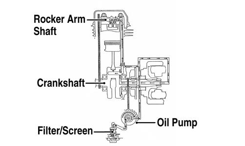
KM427A
Oil Pump
NOTE: Whenever internal engine components wear
excessively or break and whenever oil is contaminated, the oil pump should be disassembled, cleaned, and inspected.
NOTE: The oil pump is not a serviceable compo-
nent. If the pump is defective, the oil pump must be replaced.
REMOVING/DISASSEMBLING 1.Remove the oil pump from the engine (see Right-
Side Components in Engine/Transmission). 2.Remove the Phillips-head screw on the back side of the pump and separate the pump housing and cover.
Note the position of the inner and outer rotors and alignment pin for assembly. 3.Remove oil pump components. CLEANING AND INSPECTING NOTE: If any part is worn excessively, cracked, or
damaged in any way, the oil pump must be replaced.
1.Clean all oil pump components. 2.Inspect the rotors for scoring and gouges. 3.Inspect the alignment pin, driveshaft, and driven sprocket for damage. 4.Inspect the pump housing and cover for cracks or damage. ASSEMBLING/INSTALLING 1.Place the rotors into the pump housing making sure the alignment pin is in the groove of the rotor. 2.Place the cover onto the pump housing. 3.Secure the pump with the Phillips-head screw coated with red Loctite #271. 4.Install the oil pump into the engine (see Right-Side
Components in Engine/Transmission).
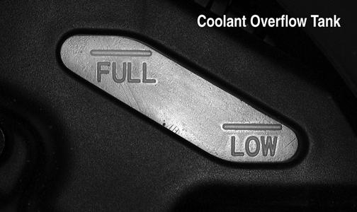
Liquid Cooling System
When filling the cooling system, use pre-mixed Arctic Cat Antifreeze. While the cooling system is being filled, air pockets may develop; therefore, run the engine for five minutes after the initial fill, shut the engine off, and fill the coolant overflow tank under the seat to the FULL line.
CAUTION
After operating the ATV for the initial 5-10 minutes, stop the engine, allow the engine to cool down, and check the coolant level. Add coolant as necessary.
KM136A
Radiator
REMOVING 1.Drain the coolant at the engine.
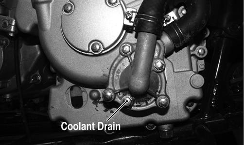
KM314A
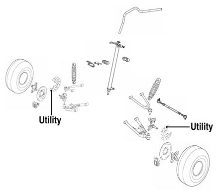
2.On the Utility, remove the front rack; then remove the front cover and fender assembly (see Steering/
Frame). 3.Remove the upper and lower coolant hoses. 4.Remove the cap screws and nuts securing the radiator to the frame. 5.Disconnect the fan wiring from the main wiring harness; then remove the radiator/fan assembly and account for the grommets and collars. 6.Remove the fan/fan shroud assembly from the radiator. CLEANING AND INSPECTING NOTE: Whenever a part is worn excessively, cracked,
or damaged in any way, replacement is necessary.
1.Flush the radiator with water to remove any contaminants. 2.Inspect the radiator for leaks and damage. 3.Inspect all hoses for cracks and deterioration. 4.Inspect all fasteners and grommets for damage or wear.
INSTALLING 1.Position the fan/fan shroud assembly on the radiator; then secure with existing hardware. 2.Place the radiator with grommets and collars into position on the frame; then install the cap screws and nuts. Tighten securely. 3.Install the upper and lower coolant hoses; then secure with hose clamps. 4.On the Utility, install the front cover and fender assembly; then install the front rack (see Steering/
Frame). 5.Fill the cooling system with the recommended amount of antifreeze. Check for leakage. 6.Connect the fan wiring to the main wiring harness. 7.Start the engine and run for 3-5 minutes; then check coolant level in the radiator and in the coolant overflow tank and add as required to the appropriate levels.
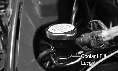
KM339A
KM136A
8.On the Utility, install the cover and rack (see Steering/
Frame).
Hoses/Thermostat
REMOVING 1.Drain approximately one U.S. qt of coolant from the cooling system. 2.Remove the two machine screws securing the thermostat housing cover to the thermostat housing.
Account for an O-ring and a thermostat.
NOTE: Whenever a part is worn excessively,
cracked, or damaged in any way, replacement is necessary.
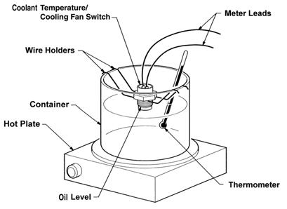
1.Inspect the thermostat for corrosion, wear, or spring damage. 2.Using the following procedure, inspect the thermostat for proper operation.
A.Suspend the thermostat in a container filled with water.
B.Heat the water and monitor the temperature with a thermometer.
C.The thermostat should start to open at 78-82° C (172-179° F) and should be full-open at 90° C (194° F).
D.If the thermostat does not open, it must be replaced. 3.Inspect all coolant hoses, connections, and clamps for deterioration, cracks, and wear. NOTE: All coolant hoses and clamps should be
replaced every four years or 4000 miles.
INSTALLING 1.Place the thermostat and O-ring into the thermostat housing; then secure the thermostat housing cover to the thermostat housing with the two cap screws.
Tighten securely. 2.Fill the cooling system with the recommended amount of antifreeze. Check for leakage.
Fan
REMOVING 1.Remove the radiator (see Radiator in this section). 2.Remove the fan assembly from the radiator. INSTALLING 1.Position the fan assembly on the radiator; then secure with existing hardware. 2.Install the radiator (see Radiator in this section).
Water Pump
REMOVING/DISASSEMBLING 1.Drain the coolant. 2.Remove the four cap screws securing the water pump case. Account for the gasket and two alignment pins. 3.Remove the impeller, washer, and seal washer.
4.Remove the mechanical seal using the following procedure.
A.Tap the tip of a small sheet metal screw into the inner-metal edge of the seal.
B.Grip the screw with a pair of vise-grip pliers and pull the seal out. Account for the pump drive seal. CLEANING AND INSPECTING NOTE: Whenever a part is worn excessively,
cracked, or damaged in any way, replacement is necessary.
1.Clean all pump components in parts-cleaning solvent. 2.Inspect the mechanical seal and pump drive seal for damage. NOTE: If the mechanical seal and/or pump drive
seal are damaged, they must be replaced as a set.
3.Inspect the impeller for corrosion or damage.
NOTE: Treat seals and O-rings with clean antifreeze
for initial lubrication.
1.Press the seal washer into the impeller by hand. 2.Install the water pump drive seal; then drive the mechanical seal into the crankcase cover using an appropriate seal driver. 3.Install the impeller with seal washer onto the water pump shaft and tighten securely. 4.Place the water pump case into position and secure with the four cap screws. 5.Fill the cooling system with the recommended amount of antifreeze. NOTE: While the cooling system is being filled, air
pockets may develop; therefore, run the engine for five minutes after the initial fill, shut the engine off, and then fill the cooling system.
6.Check the entire cooling system for leakage.
Troubleshooting
Problem: Starting impaired Condition
1. Starter jet obstructed 2. Starter jet passage obstructed 3. Starter body - carburetor leaking air 4. Starter valve not operating properly
Problem: Idling or low speed impaired Condition
1. Slow jet obstructed - loose 2. Slow jet outlet obstructed 3. Low speed fuel screw setting incorrect 4. Starter valve not fully closed 5. Float height incorrect
Problem: Medium or high speed impaired Condition
1. High RPM “cut out” against RPM limiter 2. Main jet obstructed 3. Needle jet obstructed 4. Throttle vacuum piston not operating properly 5. Filter obstructed 6. Float height incorrect 7. Starter valve not fully closed
Problem: Overflow and fuel level fluctuations Condition
1. Float valve worn - damaged 2. Float valve spring broken 3. Float not working properly 4. Float valve dirty 5. Float height too high - too low
Remedy
1.Clean jet 2.Clean passage 3.Tighten - adjust - replace gasket 4.Check - adjust valve
Remedy
1.Clean - tighten jet 2.Clean outlet 3.Adjust screw 4.Adjust valve 5.Adjust float height
Remedy
1.Shift into higher gear - decrease RPM speed 2.Clean main jet 3.Clean needle jet 4.Check piston operation 5.Clean filter 6.Adjust float height 7.Adjust valve
Remedy
1.Replace valve 2.Replace spring 3.Adjust float height - replace float 4.Clean valve 5.Adjust float height