17 minute read
Drive System

SPECIAL TOOLS A number of special tools must be available to the technician when performing service procedures in this section. Refer to the current Special Tools Catalog for the appropriate tool description.
Description
Pivot Lock Nut Wrench
Rear Axle Nut Wrench
Pinion Gear Bearing Nut Wrench Pinion Puller
V Blocks
p/n
0444-201
0444-198
0444-203
0444-202
0644-535
NOTE: Special tools are available from the Arctic
Cat Service Parts Department.
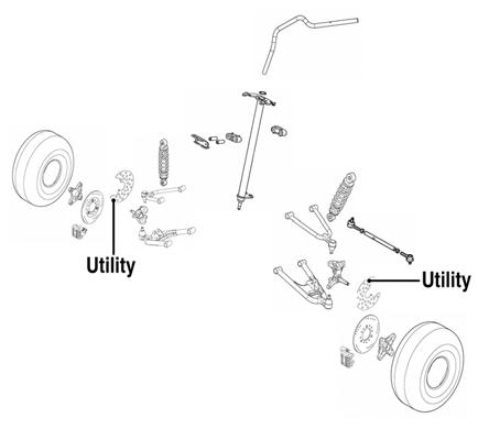
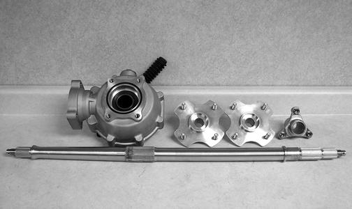
Rear Drive Assembly Schematics
DVX
Utility
KM462
KM463
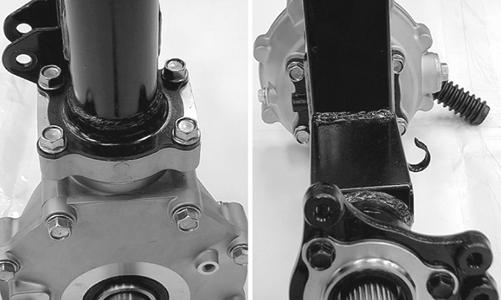
Rear Drive Axle (DVX)
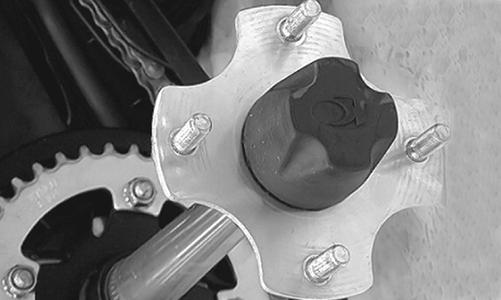
REMOVING 1.Secure the ATV on a support stand to elevate the rear wheels. 2.Engage the brake lever lock; then remove the wheels. 3.Remove the hub caps; then remove and discard the cotter pins.
Make sure the ATV is solidly supported on the support stand to avoid injury.
KM464
4.Remove the rear wheel hubs; then remove the brake caliper and lay aside. NOTE: Do not apply pressure to the brake pedal
with the caliper removed. The brake piston will be pushed out and brake fluid will be spilled.
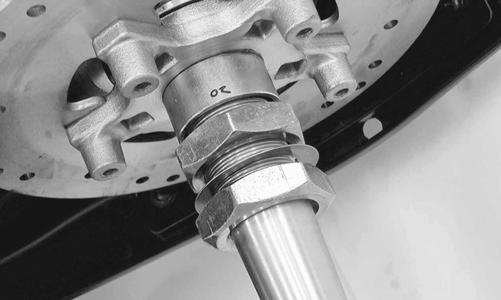
5.Remove the two axle nuts (left-hand threads).
Account for one flat washer and a spacer.
KM471
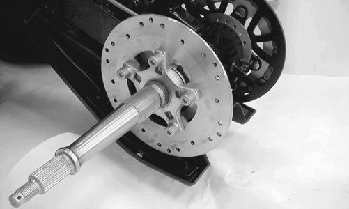
6.Remove the brake disc assembly from the axle.
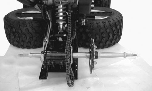
7.Loosen the drive chain (see Periodic Maintenance); then slip the chain off the sprocket and remove the axle assembly from the right side.
KM476A
8.Remove the cap screw from the rear brake caliper holder; then remove the snap ring securing the caliper holder to the axle housing.

KM481A
9.Remove the brake caliper holder and aligning collar.
Account for the O-ring.

KM483
10.Remove the four cap screws from the rear of the swing arm assembly; then remove the rear axle housing from the right side of the swing arm. 11.Remove the snap ring securing the driven sprocket to the axle; then remove the sprocket.
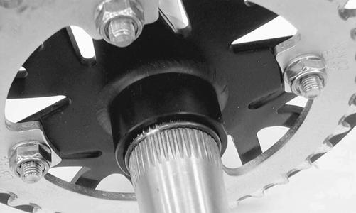
KM477
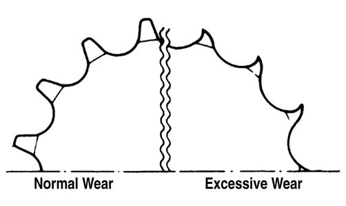
CLEANING AND INSPECTING 1.Inspect the sprocket teeth for wear. If they are worn as shown, replace the engine sprocket, rear sprocket, and drive chain as a set.
ATV2185
2.Measure the rear axle runout as shown using V blocks and a dial indicator. If the axle runout exceeds 1.5 mm (0.06 in.), the axle must be replaced.

KM480
3.Inspect the dust seals for wear or damage. If any defect is found, replace the dust seal. 4.Inspect the axle bearings by rotating them by hand. If any roughness, binding, or excessive looseness is found, replace the axle bearings. NOTE: If the axle bearings are replaced, replace the
dust seals with new ones. Always pack the bearings with a good quality wheel bearing grease.
Removing Bearings 1.Remove the dust seals using an appropriate seal removal tool; then using an appropriate driver, drive the bearings out of the axle housing. Account for one spacer. NOTE: Do not reuse bearings after removal.

KM486
2.Clean the axle housing and inspect for cracks, elongated holes, and wear in bearing bores. Installing Bearings 1.Pack the new bearings with a good quality wheel bearing grease; then install the right bearing first using an appropriate bearing installer. The sealed side of the bearing must be directed inward. 2.Install the spacer; then install the left bearing.
KM486
3.Install new dust seals and lightly coat the lips with grease. INSTALLING 1.Install the axle housing in the swing arm; then install and finger-tighten the two cap screws.
KM481A
2.Install the brake caliper holder; then install the circlip and cap screw and finger-tighten only.

KM482
3.Slide the axle into the axle housing from the right side; then apply multipurpose grease to all splined areas of the axle. 4.Install the sprocket and sprocket hub on the axle and secure with the snap ring; then install the drive chain.
KM477
5.On the left side, install the brake disc assembly and spacer; then install the brake caliper and secure with the two cap screws. NOTE: To aid in tightening the axle nuts, engage the
brake lever lock.
NOTE: It is necessary to calculate the torque value
using the following formula due to the offset of the special tool used to tighten the axle nuts.
6.Coat the axle threads with red Loctite #271 and install one axle nut (left-hand threads); then using the
Rear Axle Nut Wrench, tighten the inner axle nut to calculated specification.
KM471
L x Ts L + Ls = T
T:Torque wrench reading to be calculated Ts:Specified torque value (86 ft-lb) Ls:Tool offset length (center to center) L:Length of torque wrench (handle pivot to headcenter)

ATV2189
7.Install the washer; then install the outer axle nut and tighten to calculated specification.

KM470
8.Adjust the drive chain (see Periodic Maintenance/
Tune-Up); then tighten the two cap screws. 9.Install the wheel hubs and tighten the rear wheel hub nuts to 72 ft-lb; then install the cotter pins and hub caps.
Rear Drive Axle (Utility)
REMOVING 1.Secure the ATV on a support stand to elevate the rear wheels.
! WARNING
Make sure the ATV is solidly supported on the support stand to avoid injury.
2.Compress the brake lever and engage the brake lever lock; then remove the rear wheels and hub caps. 3.Remove the cotter pins and rear hub nuts; then remove the hubs. 4.Disengage the brake lever lock; then remove the rear brake calipers and brake disc. NOTE: Do not apply the brakes with the calipers
removed. The brake pistons will be pushed out and brake fluid will be spilled.
KM505
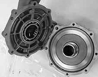
5.Remove the rear drive gear case; then drain the gear case. 6.Loosen the clamp securing the joint boot to the swing arm; then slip the boot off the swing arm.

KM504
7.Remove the clamp securing the brakeline hose to the swing arm; then remove the lower rear shock absorber mounting nut and bolt.
KM505
8.Remove the left and right pivot caps; then remove the right-side pivot bolt.

KM509
12.Remove the eight cap screws securing the swing arm to the final drive gear case.
KM506
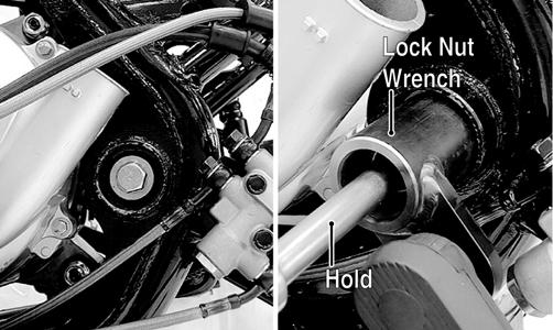
9.From the left side, remove the pivot lock nut using
Pivot Lock Nut Wrench; then remove the left pivot adjusting bolt.

KM533B
10.Remove the swing arm assembly. Account for the driveshaft spring.

KM513
13.Support the swing arm from the right side; then using a rubber mallet, drive the axle shaft from the swing arm tube. Account for two O-rings.

KM536
14.Place the right end (shorter length) of the axle on a wood block; then using a rubber mallet, drive the gear case from the axle.
KM538
CAUTION
Support the gear case by hand or damage to the gear case could occur as it will fall free once it clears the splined portion of the axle.
CLEANING AND INSPECTING
NOTE: Whenever a part is worn excessively,
cracked, or damaged in any way, replacement is necessary.
1.Clean all parts with parts-cleaning solvent and dry with compressed air. 2.Inspect all seals for nicks, tears, or deterioration.

KM519
3.Inspect all splines and hubs for excessive wear, chips, cracks, or distortion.

KM540
4.Check that all bearings turn freely and smoothly and are not worn, discolored, or missing dust seals. 5.Inspect brake components for leaks, excessive wear, or discoloration. 6.Check the axle shaft for runout using a dial indicator and suitable supports. Maximum runout is 3 mm (0.12 in.). NOTE: Axle runout is equal to 1/2 the total dial indi-
cator reading.

KM543
7.Check the final drive gear case assembly for smooth gear operation. If gears are noisy or if there is any catching or binding, the gear case assembly must be repaired. DISASSEMBLING 1.Remove the cap screws securing the gear case cover to the gear case; then remove the gear case cover and right ring gear shim.

KM919A
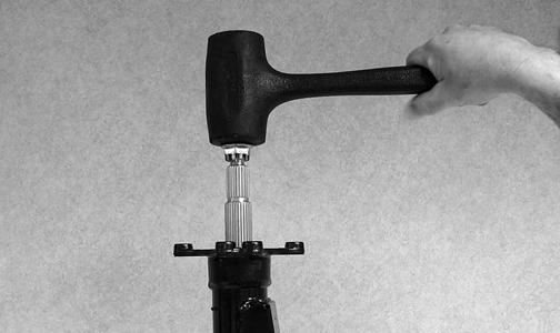
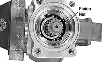
2.Remove the oil seal from the front of the gear case; then using the Pinion Gear Bearing Nut Wrench, remove the pinion nut.
KM920A

KM921
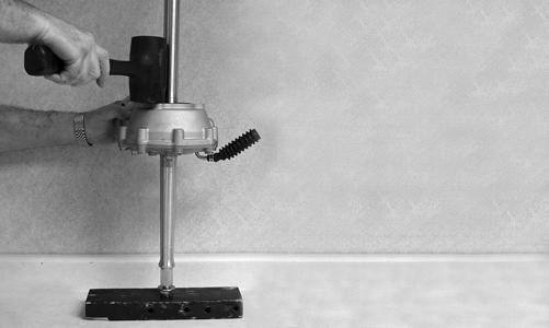
3.Remove the pinion shaft using the pinion puller; then using a three-jaw puller, remove the pinion bearing.
Account for the pinion shim.


KM923

KM924A
4.Remove the oil seals from the case and cover; then drive the bearings out of the case.

KM925
KM926
KM927

KM928
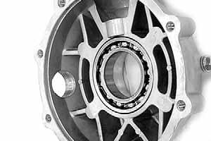
5.Heat the gear case to approximately 180° F and using a blind-bushing puller, remove the pinion needle bearing. CLEANING AND INSPECTING 1.Clean all components in parts cleaning solvent and dry with compressed air. 2.Inspect all bearings for excessive wear, discoloration, roughness in turning, or flaking. 3.Inspect gears for excessive wear, chipped teeth, flaking, or discoloration. 4.Inspect the gear case and cover for cracks, warpage, or scoring of bearing bores. 5.If seals have not been removed and will be reused, inspect for nicks, tears, missing tension springs, or excessive wear on lips. ASSEMBLING 1.Drive the bearings into the gear case and gear case cover using an appropriate bearing driver. Make sure the bearing is firmly seated.
KM926
KM928
2.Apply grease to the seal lips; then using a seal driver, drive the seals into the gear case and cover (flat side out) until flush with the seal bore.

KM927A

KM925A
3.Drive a new pinion needle bearing into the gear case; then apply molybdenum disulfide grease to the needle bearing. Secure with the snap ring.
4.If the pinion bearing was removed from the pinion, install the shim and bearing on the pinion shaft with the marked-side of the bearing directed toward the front of the pinion shaft.
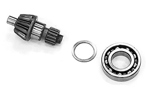
KM924

KM935
NOTE: When the gear set, ring gear, ring gear bear-
ing, and/or gear case is being replaced, use a 2 mm (0.08 in.) thick shim for initial set-up.
5.Drive the pinion assembly into the gear case seating the bearing firmly; then secure with a new lock nut and using the pinion lock nut wrench, tighten to 72 ft-lb.
KM920A KM921
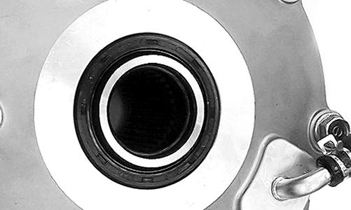
6.Apply grease to the pinion seal lips and install into the gear case until fully seated; then apply a light coating of machinist’s layout dye or paste to several ring gear teeth. 7.Install the proper shims on the ring gear and install into the gear case; then install the case cover and secure with the case cap screws. Tighten in a crisscross pattern while rotating the pinion gear. Checking Tooth Contact 1.Rotate the ring gear several turns in either direction; then check gear contact through the oil filler hole. 2.Examine the tooth contact pattern in the dye and compare the pattern to the illustrations.
ATV-0103
ATV-0105
Backlash Ring Gear Left Side Ring Gear Right Side
Insufficient Decrease Shim Increase Shim Excessive Increase Shim Decrease Shim
ATV-0104
Correcting Tooth Contact
NOTE: If tooth contact pattern is comparable to the
correct pattern illustration, no correction is necessary.
If tooth contact pattern is comparable to an incorrect pattern, correct tooth contact according to the following chart.
Tooth Contact
Contacts at Top Contacts at Root
Shim Correction
Decrease Shim Thickness Increase Shim Thickness
After tooth contact is corrected, gear backlash must be checked. Checking Backlash 1.Mount a dial indicator through the oil fill plug to contact a tooth on the ring gear; then “zero” the dial indicator.

KM936
2.While locking the pinion shaft to prevent it from turning, rock the ring gear back and forth and record the measurement. Standard backlash should be 0.050.25 mm (0.002-0.010 in.). Maximum service limit is 0.4 mm (0.016 in.). 3.Remove the dial indicator and rotate the ring gear 120°; then repeat steps 1-2. 4.Repeat step 3 for a total of three measurements; then compare the difference between the three. Maximum allowable difference is 0.2 mm (0.08 in.). NOTE: If the difference in measurements exceeds
specifications, the bearings are not installed squarely or the gear case is warped. If backlash is not within specifications, correct using the following chart.
NOTE: Always change both shims by the same
amount on opposite sides. If left shim is increased, right shim must be decreased by the same amount.
5.After backlash is corrected, recheck gear tooth contact. Repeat Correcting Tooth Contact and Checking
Backlash until both are within specifications. 6.When tooth contact and backlash are within specification, remove the cap screws securing the cover to the gear case. 7.Clean any oil from the mating surfaces; then apply an even coat of silicone sealant to the mating surfaces and install the gear case covers. 8.Install six 8 mm and two 10 mm cap screws and while rotating the pinion gear, tighten in a crisscross pattern to the specified torque (8 mm cap screws to 19 ft-lb, 10 mm cap screws to 36 ft-lb). REPLACING SWING ARM SEALS AND BEARINGS To replace damaged or worn seals and bearings in the swing arm assembly, use the following procedure. 1.Remove the dust seals from the swing arm pivot; then using a slide hammer and bearing puller, remove the pivot bearings.

KM521
2.Drive in new pivot bearings until fully seated; then install new dust seals.

3.Remove the three cap screws, the dust plate, and one
O-ring from the left axle housing on the swing arm; then from the right side, drive out the axle bearing.
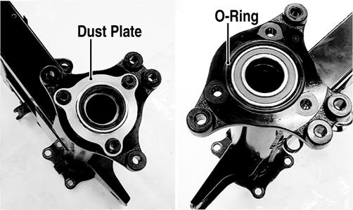
KM523A
4.Using a suitable bearing driver, install the new axle bearing into the axle housing; then install the O-ring and dust plate. Tighten the three cap screws securely. INSTALLING 1.Install new O-rings in the grooves of the gear case; then grease the center splines of the axle and install in the gear case from the left side.

KM527
2.Install the rear axle and gear case into the right side of the swing arm; then secure the gear case to the swing arm assembly with the eight cap screws.
Tighten to 50 ft-lb.

KM528A
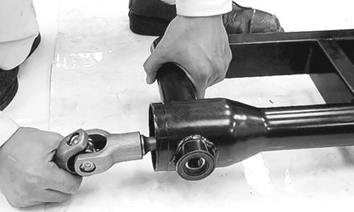
3.Apply grease to the universal joint splines and driveshaft splines; then install the driveshaft spring into the driveshaft.

KM529
NOTE: Apply a liberal amount of grease to the drive-
shaft splines and the driveshaft spring. This will aid in keeping the spring in position while assembling.
4.Insert the driveshaft assembly into the swing arm tube; then engage the driveshaft splines with the pinion shaft splines in the rear drive gear case.
KM530
5.Pack approximately 3g (0.1 oz) of grease into each swing arm pivot bearing cavity; then apply grease to the lips of the dust seals.

KM531
6.Align the swing arm assembly in the frame and engage the universal joint onto the splines of the secondary driven bevel gear shaft.

KM532
7.Install the right pivot bolt and left pivot adjusting bolt and tighten securely; then move the swing arm up and down to seat the bearings. Tighten the left pivot bolt to 36 in.-lb and the right pivot bolt to 82 ftlb. 8.Install the left pivot lock nut; then while holding the left pivot adjusting bolt, use Pivot Lock Nut Wrench to tighten the lock nut to 82 ft-lb.
KM533B
9.Install the shock absorber using the existing hardware and tighten to 29 ft-lb; then install the brakeline hose clamp on the swing arm and tighten securely.

KM505A
10.Tighten the final drive gear case drain plug securely; then remove the fill plug and level plug.

KM131A
11.Pour the recommended gear lubricant into the fill hole until lubricant is visible on the threads of the level hole; then install the level plug and the fill plug and tighten securely. 12.Install the rear drive gear case guard and tighten the cap screws securely. 13.Apply grease to the brake disc hub and wheel hubs; then install the disc and rear hubs.

KM502
14.Install the hub nuts and tighten to 72 ft-lb; then install new cotter pins and bend as shown.
KM469
15.Install the rear brake calipers and tighten to 25 ft-lb. 16.Install the rear hub caps; then install the rear wheels and tighten to 32 ft-lb. 17.Remove the ATV from the support stand.
Troubleshooting Drive System
Troubleshooting Brake System
Problem: Power not transmitted from engine to wheels Condition Remedy
1. Rear axle shaft serration worn - broken 1.Replace shaft
Problem: Braking poor Condition Remedy
1. Pad worn 1.Replace pads 2. Pedal free-play excessive 2.Adjust free-play 3. Brake fluid leaking 3.Repair - replace hydraulic system 4. Hydraulic system entrapped air 4.Bleed hydraulic system 5. Master cylinder/brake cylinder seal worn 5.Replace appropriate cylinder
Problem: Brake lever travel excessive Condition Remedy
1. Hydraulic system entrapped air 2. Brake fluid low 3. Brake fluid incorrect 4. Piston seal - cup worn 1.Bleed hydraulic system 2.Add fluid to proper level/bleed system 3.Replace with correct fluid 4.Replace master cylinder
Problem: Brake fluid leaking Condition Remedy
1. Connection joints loose 1.Tighten joint 2. Hose cracked 2.Replace hose 3. Piston seal worn 3.Replace master/brake cylinder