14 minute read
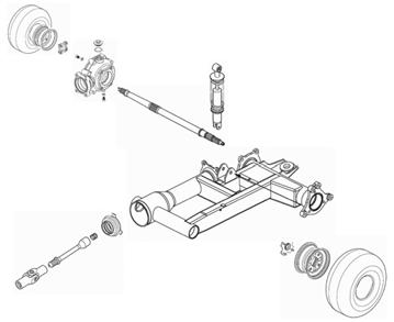
Steering/Frame/Controls

The following steering components should be inspected periodically to ensure safe and proper operation.
A.Handlebar grips not worn, broken, or loose.
B.Handlebar not bent or cracked and has equal and complete full-left and full-right capability.
C.Steering post bearing assembly/bearing housing not broken, worn, or binding.
D.Ball joints not worn, cracked, or damaged.
E.Tie rods not bent or cracked.
F.Knuckles not worn, cracked, or damaged.
G.Cotter pins not damaged or missing. The frame, welds, and racks should be checked periodically for damage, bends, cracks, deterioration, broken components, and missing components.
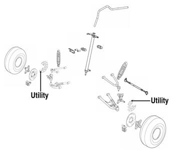
Steering Post/Tie Rods
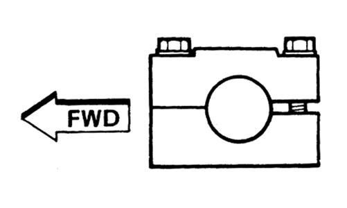
KM598E
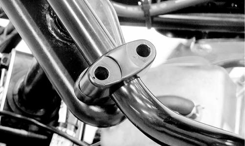
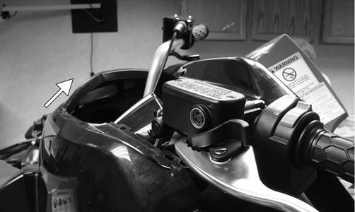
REMOVING 1.On the Utility, remove the front rack and front center panel (see Body in this section). On the DVX, proceed to step 2. 2.Remove the steering post cover (DVX) or the instrument pod (Utility) (see Steering Post Cover/Instrument Pod in this section); then remove the cap screws securing the handlebar to the steering post.
Account for two handlebar holders.
KM189A
3.Lift the handlebar out of the lower handlebar holders and lay the handlebar forward. 4.Remove the cotter pins and slotted nuts securing the tie rod ends to the steering post arm; then disconnect the tie rods from the arm.
KM590
5.Remove the cotter pin and slotted nut from the lower end of the steering post; then remove the upper steering shaft support block. Account for a cable guide, two steering support blocks, and the upper steering post bushing.
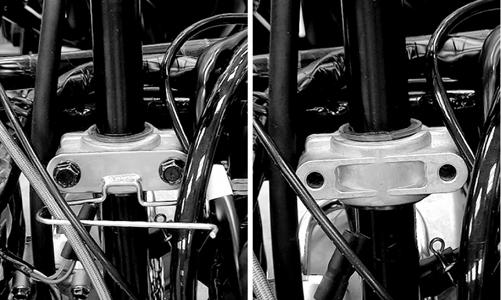
KM588
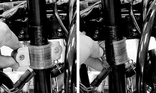
KM589
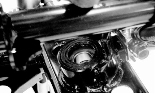
6.Remove the steering post from the ATV. CLEANING AND INSPECTING NOTE: Whenever a part is worn excessively, cracked,
or damaged in any way, replacement is necessary.
1.Wash the tie rod ends in parts-cleaning solvent. Dry with compressed air. Inspect the pivot area for wear.
Apply a low-temperature grease to the ends. ! WARNING
Always wear safety glasses when using compressed air.
2.Inspect the tie rods for damaged threads or wear. 3.Inspect the tie rods for cracks or unusual bends. 4.Inspect all welded areas for cracks or deterioration. 5.Inspect the steering post and steering-post holders for cracks, bends, or wear. 6.Inspect the handlebar clamps for cracks or wear. 7.Inspect the handlebar for cracks, wear, or unusual bends. 8.Inspect the handlebar grips for damage or wear. 9.Inspect the lower steering post support bearing and seal for wear or cracks. INSTALLING 1.Apply a thin coat of grease to the lips of the lower steering post seals; then lower the steering post into position in the lower steering post bearings.
KM593
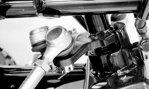
2.Apply a thin coat of grease to the upper steering post bushing; then secure the steering post with the support blocks and existing hardware. Tighten to 17 ft-lb.
KM589
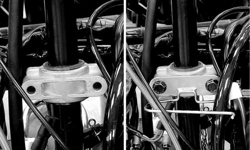
KM595
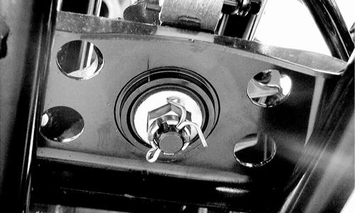
3.Install the slotted nut on the lower steering post and tighten to 50 ft-lb; then install a new cotter pin.
KM591
4.Place the inner tie rod ends into the steering post arm and tighten the slotted nuts to 15 ft-lb; then install new cotter pins.
KM590
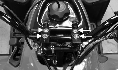
5.Install the handlebar and tighten the clamp cap screws to 18 ft-lb making sure to tighten the front cap screws first.
KM587
KM597
6.Install the instrument pod (Utility) or steering post cover (DVX). 7.Install the center panel and front rack (Utility).
Measuring/Adjusting Toe-In/Toe-Out
1.With the ATV on a level surface, center the handlebar for straight ahead using a suitable means of measuring centering; then adjust tire pressure to specifications (see General Information). 2.Support the front of the ATV with the wheels free to rotate; then center and secure the handlebar. 3.Measure the distance (A) and (B) between the front wheels; then subtract distance (B) from (A). Distance
A - Distance B = Toe-In.
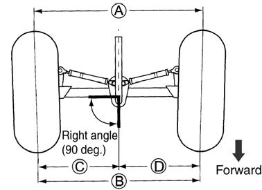
ATV2205
4.Adjust toe-in to 15 mm (0.60 in.); then measure distances (C) and (D). Distances (C) and (D) should be equal. 5.After all the adjustments are to specifications, tighten the tie-rod lock nuts to 15 ft-lb. NOTE: Prior to locking the jam nuts, make sure the
ball joints are at the center of their normal range of motion and at the correct angle.
NOTE: The front wheels do not have to be removed
to adjust the tie rod. Also, care should be taken not to disturb the handlebar position.
Body
REMOVING (DVX) 1.Remove the seat; then remove the battery hold-down strap, battery, and starter relay. Lay the relay aside without disconnecting the wiring. NOTE: Always remove the negative battery cable
first; then the positive cable.
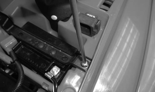
SP107
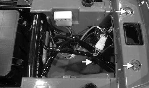
2.Remove the CDI, start-in-gear relay, and fuse block and lay aside without disconnecting the wires; then remove the shift knob. 3.Remove the six cap screws securing the body to the top of the frame; then remove the cap screws from the bottom of the battery box.
KM782A
KM790A
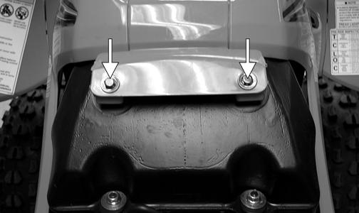
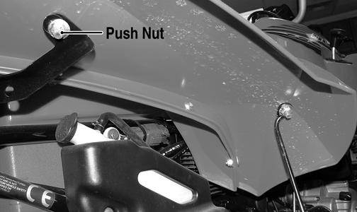
4.Remove four flange nuts and cap screws securing the rear fender support; then remove the push nuts from the mounting studs at the front of the rear fenders.
KM785A
KM784A
5.Remove the hardware securing the front fenders to the fender supports; then disconnect the headlight.
KM352A
6.Turn the handlebar to the left; then raise the body turning it to the right and lift clear of the handlebar. REMOVING (Utility) 1.Remove the seat; then remove the battery box cover.
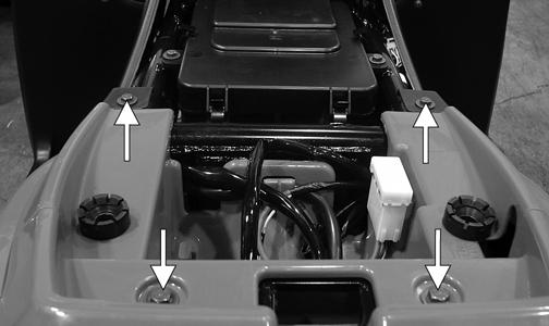
KM793A
2.Disconnect the negative battery cable first; then the positive cable. 3.Remove the battery hold-down strap; then remove the battery. 4.Remove the front and rear racks; then remove the cap screws securing the front center panel and remove the panel.
KM308A
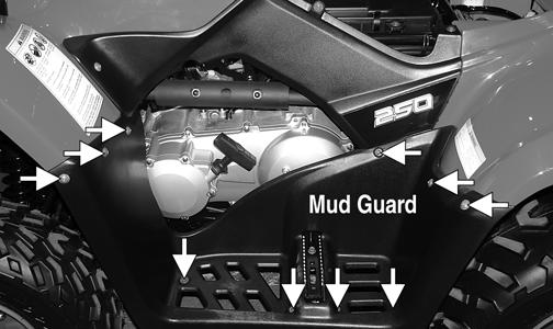
5.Remove the cap screws and flange nuts securing the mud guards to the front and rear fenders; then remove the cap screws securing the mud guards to the front rests and remove the mud guards.
KM789A
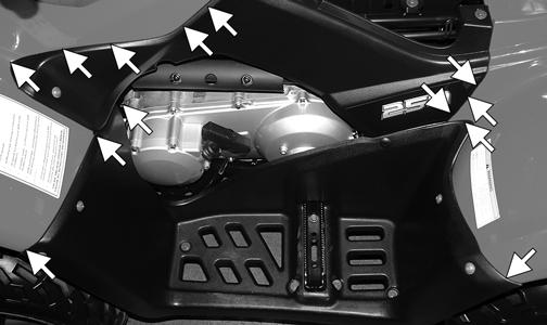
6.Remove the side panels; then remove the cap screws and flange nuts securing the front and rear fenders to the frame and fender supports.
KM799B
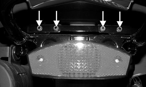
7.Disconnect the left and right headlight connectors; then disconnect the taillight. 8.Remove the gas tank cover; then remove the shift knob and front and rear fenders.
KM797
CLEANING AND INSPECTING
NOTE: Whenever a part is worn excessively,
cracked, or damaged in any way, replacement is necessary.
1.Clean all body components with soap and water. 2.Inspect the body and fenders for cracks. 3.Inspect threaded areas of all mounting studs for stripping. 4.Inspect for missing decals. INSTALLING (DVX) 1.Fit the body over the handlebar and rotate into normal mounting position. 2.Using the existing hardware, secure the front fenders to the fender supports; then connect the headlight. 3.Using the existing hardware, secure the rear fenders to the forward fender supports; then secure the rear fender to the frame with four cap screws and flange nuts. Tighten securely. 4.Install the six cap screws securing the body to the top of the frame. Tighten securely. 5.Install the fuse block, start-in-gear relay, and the
CDI; then install the body mounting cap screw into the bottom of the battery box. 6.Install the battery and battery hold-down strap; then connect the positive battery cable and the negative battery cable. NOTE: Always install the positive cable first; then
install the negative cable.
7.Install the seat making sure it is latched securely. INSTALLING (Utility) 1.Place the front and rear fenders into position on the frame and secure with the existing hardware; then install the gas tank cover. Tighten all fasteners securely. 2.Connect the headlight and taillight connectors; then install the shift knob. 3.Making sure the locating tabs engage the appropriate slots in the fenders, install the side panels.
KM340A
4.Install the mud guards and secure to the fenders and foot rest supports with the existing hardware. Make sure all locating tabs are appropriately engaged with the fenders and side panels.
KM789A
KM788A
5.Install the front center cover; then install the front and rear racks. Tighten all fasteners securely. 6.Install the battery; then connect the positive battery cable, negative battery cable, and battery hold-down strap. NOTE: Always install the positive cable first; then
install the negative cable.
7.Install the battery cover; then install the seat making sure it locks securely in place.
Steering Post Cover/ Instrument Pod
REMOVING (DVX) 1.Remove the two reinstallable rivets on the rear of the steering post cover; then lift up and push the assembly forward to remove. 2.Disconnect the wire connectors from the indicator lights and from the ignition switch. REMOVING (Utility) 1.Remove the reinstallable rivet on the front of the instrument pod and the two cap screws on the rear; then lift the assembly off and disconnect the speedometer cable. 2.Remove the self-tapping screw securing the LCD gauge assembly to the instrument pod; then remove the LCD gauge.
NOTE: The LCD gauge is not a serviceable compo-
nent. If any functions are incorrect or indicator lights do not illuminate, the LCD gauge must be replaced.
INSPECTING/SERVICING (DVX) 1.Remove the two self-tapping screws securing the indicator lamp assembly in the steering post cover. 2.Inspect the bulbs for blackening or burn out. Replace as required. 3.Inspect the indicator lamp holder for loose sockets, broken wires, or loose connections. Replace as required. INSPECTING (Utility) The LCD gauge is not a serviceable component. To inspect the LCD gauge, see Electrical System. INSTALLING (DVX) 1.Connect the indicator lamp connectors; then connect the main harness connector to the ignition switch. 2.Place the steering post cover onto the mounting bracket; then secure with the reinstallable rivets. INSTALLING (Utility) 1.Connect the main harness connector to the LCD gauge; then connect the ignition harness to the ignition connectors. 2. Place the instrument pod onto the mounting bracket; then secure with the reinstallable rivet and two cap screws.
Front Brake Lever/Master Cylinder Assembly
NOTE: The master cylinder is a non-serviceable
component; it must be replaced as an assembly.
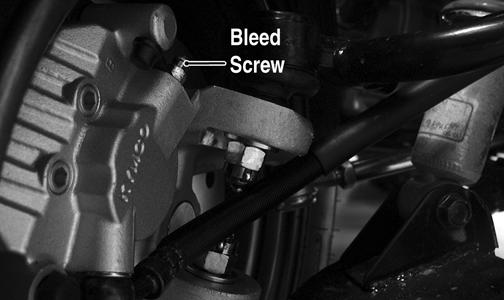
REMOVING 1.Connect a clear hose to the bleed screw on either front brake caliper; then open the bleed screw and pump the brake fluid into a suitable container. Close the bleed screw.
CAUTION
Brake fluid is highly corrosive. Do not spill brake fluid on any surface of the ATV.
NOTE: Do not reuse brake fluid. When exposed to
air, brake fluid rapidly absorbs moisture.
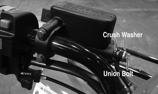
2.Remove the brakeline hose union bolt; then remove the cap screws securing the master cylinder assembly to the handlebar. Discard the crush washers from the union bolt.
KM800A
3.Remove the brake lever, brakelight switch, and brake lever lock. INSPECTING NOTE: Whenever a part is worn excessively,
cracked, or damaged in any way, replacement is necessary.
1.Inspect the pivot bolt securing the brake lever for wear. 2.Inspect the brake lever for elongation of the pivot hole. 3.Inspect the reservoir for cracks and leakage. 4.Inspect the brake hose for cracks and deterioration and the condition of the fittings (threaded and compression). 5.Inspect the brakelight switch for corrosion, cracks, missing or broken mounting tabs, or broken and frayed wiring. NOTE: If the brakelight switch is determined to be
not serviceable, see Electrical System.
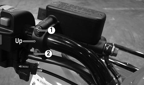
INSTALLING 1.Install the brakelight switch on the master cylinder; then install the brake lever and brake lever lock. 2.Install the master cylinder assembly on the handlebar engaging the alignment stud in the hole in the handlebar; then secure with the master cylinder clamp and two cap screws. Make sure the UP arrow on the clamp is directed upward.
KM800B
3.Tighten the cap screw (1) to 13 ft-lb; then tighten the cap screw (2) to 13 ft-lb.
KM800B
4.Using new crush washers, secure the brake hose to the master cylinder with the brake hose union bolt.
Tighten to 25 ft-lb.
KM800A
5.Fill the master cylinder with DOT 4 brake fluid; then bleed the system (see Periodic Maintenance).
Auxiliary Brake Pedal/ Master Cylinder Assembly
NOTE: The auxiliary brake master cylinder is a non-
serviceable component; it must be replaced as an assembly.
REMOVING 1.Connect a clear plastic hose to the appropriate bleed screw on the rear brake caliper; then loosen the bleed screw and pump the foot brake until the fluid is pumped into a suitable container.
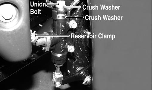
2.Compress the reservoir clamp and remove the reservoir hose; then remove the union bolt. Account for and discard two crush washers.
CAUTION
Brake fluid is highly corrosive. Do not spill brake fluid on any surface of the ATV.
KM801A
3.Remove the cotter pin from the clevis pin and remove the clevis pin; then remove the two cap screws securing the master cylinder to the frame and remove the master cylinder.
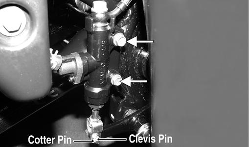
KM801B
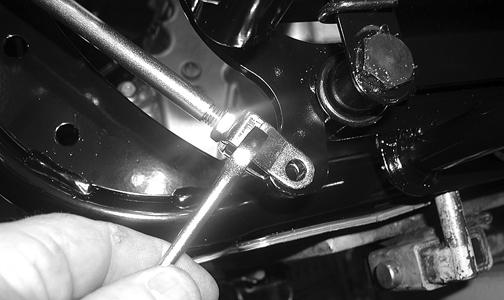
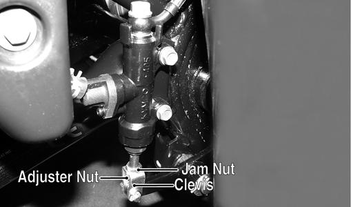
4.Loosen the jam nut; then remove the clevis and adjuster nut. INSTALLING 1.Install the jam nut; then install the clevis and adjuster nut. Finger-tighten only at this time. 2.Secure the master cylinder to the frame with the two cap screws and tighten securely. 3.Using two new crush washers, connect the brake hose to the master cylinder with the union bolt; then making sure the spring clamp is seated securely, connect the reservoir hose to the master cylinder.
Tighten the union bolt to 25 ft-lb. 4.Making sure the brake pedal is fully released and against the stop, turn the clevis and adjuster nut until the hole in the clevis is aligned with the hole in the brake pedal lever; then tighten the jam nut securely.
CD476
KM801C
5.Fill the master cylinder reservoir with DOT 4 brake fluid and bleed the system (see Periodic Maintenance/Tune-Up).
Throttle Control
REMOVING 1.Remove the boot from the throttle cable adjuster; then loosen the jam nut and turn the adjuster completely in to loosen the cable. 2.Remove the three machine screws securing the cover to the throttle control; then remove the cover and disengage the throttle cable from the throttle arm. 3.Turn the cable adjuster out of the throttle control housing; then remove the two machine screws securing the throttle control to the handlebar and remove the throttle control. INSTALLING 1.Making sure the throttle housing upper flat aligns with the alignment mark on the handlebar, place the throttle control into position on the handlebar and secure with the two machine screws; then tighten the machine screws securely.
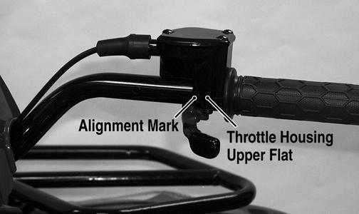
KM122B
2.Thread the throttle cable into the throttle housing and turn the adjuster completely in; then connect the throttle cable to the throttle arm. 3.Install the throttle housing cover; then adjust the throttle cable (see Fuel/Lubrication/Cooling).
Troubleshooting
Problem: Handling too heavy or stiff Condition Remedy
1. Front wheel alignment incorrect 1.Adjust alignment 2. Lubrication inadequate 2.Lubricate appropriate components 3. Tire inflation pressure incorrect 3.Adjust pressure 4. Tie rod ends seizing 4.Replace tie rod ends 5. Linkage connections seizing 5.Repair - replace connections
Problem: Steering oscillation Condition Remedy
1. Tires inflated unequally 1.Adjust pressure 2. Wheel(s) wobbly 2.Replace wheel(s) 3. Wheel hub cap screw(s) loose - missing 3.Tighten - replace cap screws 4. Wheel hub bearing worn - damaged 4.Replace bearing 5. Tie rod ends worn - loose 5.Replace - tighten tie rod ends 6. Tires defective - incorrect 6.Replace tires 7. A-arm bushings damaged 7.Replace bushings 8. Bolts - nuts (frame) loose 8.Tighten bolts - nuts
Problem: Steering pulling to one side Condition Remedy
1. Tires inflated unequally 1.Adjust pressure 2. Front wheel alignment incorrect 2.Adjust alignment 3. Wheel hub bearings worn - broken 3.Replace bearings 4. Frame distorted 4.Repair - replace frame 5. Shock absorber defective 5.Replace shock absorber
Problem: Steering impaired Condition Remedy
1. Tire pressure too high 1.Adjust pressure 2. Steering linkage connections worn 2.Replace connections 3. Cap screws (suspension system) loose 3.Tighten cap screws
Problem: Tire wear rapid or uneven Condition Remedy
1. Wheel hub bearings worn - loose 1.Replace bearings 2. Front wheel alignment incorrect 2.Adjust alignment
Problem: Steering noise Condition Remedy
1. Cap screws - nuts loose 1.Tighten cap screws - nuts 2. Wheel hub bearings broken - damaged 2.Replace bearings 3. Lubrication inadequate 3.Lubricate appropriate components